Download
1 / 31
310 likes | 510 Views
Applications of optical technology in accelerator instrumentation and diagnostics. John Byrd Lawrence Berkeley National Laboratory. Introduction. Accelerator development has a long history of adopting and adapting new technologies to make bigger, better, and cheaper machines.

E N D
Applications of optical technology in accelerator instrumentation and diagnostics John Byrd Lawrence Berkeley National Laboratory DPF2011, Providence, RI
Introduction • Accelerator development has a long history of adopting and adapting new technologies to make bigger, better, and cheaper machines. • Revolutions in two fields are being applied towards accelerators: • Ultrastable mode-locked lasers • Optical fiber networking technology • Optical technology is approaching a similar level as RF and microwave technology to controlling accelerators.
Selected topics in optical accelerator instrumentation • Time • Femtosecond timing distribution for accelerators using stabilized optical fiber links (LC, LPA, XFELs) • Optical techniques for measuring ultrafast electron bunches (LC, LPA, XFELs) • Intensity • Laser stripping of high intensity H- beams (PX, ADS) • Laser diagnostics of H- beams (PX, ADS)
High precision timing and synchronization • Next generation linacs require unprecedented level of synchronization to achieve high beam quality: Linear colliders, FELs, and LPAs (staging) • LC needs <50 fsec relative stability in linac systems • CLIC needs <15 fsec 1 psec=0.5 deg @1.3 GHz Master Stabilized link Stabilized link Stabilized link Stabilized link
X-ray/optical Pump-probe Pump laser Laser pump pulse ∆t Electron linac/undulator Master • Ultrafast laser pulse “pumps” a process in the sample • Ultrafast x-ray pulse “probes” the sample after time ∆t • By varying the time ∆t, one can make a “movie” of the dynamics in a sample. • Synchronism is achieved by locking the x-rays and laser to a common clock.
Time and Frequency Domain Stabilized Links 50% reflective mirror CW Signal Source Optical fiber Measure relative forward/reverse phase Compensate fiber length • Fiber links can be stabilized based on the revolution in metrology time and wavelength standards over the past decade. Maintain constant number of optical wavelengths 50% reflective mirror Pulsed Signal Source Optical fiber Measure repetition rate compared to source Compensate fiber length Maintain constant repetition rate of forward/reflected pulses Correction BW limited to R/T travel time on fiber (e.g. 1 km fiber gives 100 kHz)
Three Challenges • Provide long-term stable clock over entire accelerator complex: injector, linac, diagnostics, and lasers • Use stabilized links to maintain stable relative phase • Laser-laser stability should be <10 fsec (maybe better). • RF cavity stability should be <50-100 fsec. • Lock remote clients to stable clock • Advanced digital controllers (RF and mode-locked laser oscillators) • Direct seeding of remote lasers • Measure resulting electron and photon timing stability • Femtosecond electron arrival time and bunch length and energy spread monitors • Femtosecond x-ray arrival time, pulse length, spectrometer
Single Channel Link Receiver Transmitter Signal fiber RF phase detect and correct CW laser AM d2 FS FRM FRM 0.01C Rb lock Beat fiber 0.01C optical delay sensing fFS fRF d1 • FRM is Faraday rotator mirror (ends of the Michelson interferometer) • FS is optical frequency shifter • CW laser is absolutely stabilized • Transmitted RF frequency is 2856 MHz • Detection of fringes is at receiver • Signal paths not actively stabilized are temperature controlled
RF Transmission tests 2km 0.01C 0.01C RF phase detection and correction phase data 1560nm RF in ref. arm RF in CW fiber laser +50MHz AM RF in delay data ref. arm +50MHz Rb freq. locker optical delay sensing • Compare relative phase of 2856 MHz transmitted long and short stabilized links. • Shift RF phase to compensate for link variation • Compensate for GVD correction • Actively calibrate RF phase detection front end (mixers, splitters, etc.)
RF Transmission results Relative delay of 2km and 2 meter fibers 61 hours
Detailed results delay error, femtoseconds time, hours • 1kHz bandwidth • For 2.2km, 19fs RMS over 60 hours • For 200m, 8.4fs RMS over 20 hours • 2-hour variation is room temperature 2.2km 200m 2km data Allan deviation time, seconds
All-optical lock schemes • Synchronization of lasers with RF signals limited by resolution in phase(0.01 deg@3GHz=10 fsec) • Go to optical frequencies… • Create a beat wave generated from two mode-locked comb lines (up to a few THz) • Lock the beat wave of one laser with a remote laser
Electro-Optic Detection of Direct Beam Fields Spectral Decoding complexity demonstrated time resolution FELIX DESY LBNL ... Spatial Encoding SLAC DESY LBNL, ... Temporal Decoding FELIX DESY RAL(CLF)MPQ Jena, ... spectral upconversion
EO Sampling: spectral encoding • Probe laser is optically stretched with time-wavelength correlation • EO effect is imprinted on pulse • Correlation is imaged from an optical spectrometer.
Spectral upconversion diagnostic Aim to measure the bunch Fourier spectrum... use long pulse, narrow band, probe laser same physics as “standard” EO ... accepting loss of phase information & explicit temporal information ... gaining potential for determining information on even shorter structure ... gaining measurement simplicity • laser complexity reduced, reliability increased • laser transport becomes trivial (fibre) • problematic artefacts of spectral decoding become solution NOTE: the long probe is converted to optical replica Courtesy, S. Jamison
Spectral upconversion diagnostic Results from experiments at FELIX (Feb 2009) Theory / Expt. comparison in FEL’09; (Appl. Phys. Lett.) FELIX temporal profile sum frequency mixing difference frequency mixing inferredFELIXspectrum S.P. Jamison, G. Berden, P. J. Phillips, W.A. Gillespie, A.M. MacLeod APL 2010: 96(23): 231114- 231114-3
Group-velocity mismatch Second harmonic created just as pulse enters crystal (overlaps the input pulse) As the pulse enters the crystal: Crystal Second harmonic pulse lags behind input pulse due to GVM As the pulse leaves the crystal: Inside the crystal the two different wavelengths have different group velocities. Define the Group-Velocity Mismatch (GVM):
Alternative method for phase-matching: periodic poling Recall that the second-harmonic phase alternates every coherence length when phase-matching is not achieved, which is always the case for the same polarizations—whose nonlinearity is much higher. Periodic poling solves this problem. But such complex crystals are hard to grow and have only recently become available.
Example product • Covesion MgO:PPLN for Second Harmonic Generation
Example: Beam Arrival Time Monitorusing MLL pulses • Florian Loehl, et al., PRL 104, 144801 (2010)
Sub-fsec arrival monitor • Sensitivity of e-beam arrival monitors proportional to reference frequency. • Use THz beat wave as a reference frequency. • Electro-optically modulate beat wave with e-beam electric field. fsec e-bunch
Frequency-Resolved Optical Gating (FROG) FROG involves gating the pulse with a variably delayed replica of itself in an instantaneous nonlinear-optical medium and then spectrally resolving the gated pulse vs. delay. Pulse to be measured SHG FROG is simply a spectrally resolved autocorrelation. Beam splitter Camera E(t–t) SHG crystal Spec- trometer E(t) Esig(t,t)= E(t)E(t-t) Variable delay, t Use any ultrafast nonlinearity: Second-harmonic generation, etc.
SHG FROG Measurements of a Free-Electron Laser 5 5 4 4 3 3 2 2 1 1 0 0 Richman, et al., Opt. Lett., 22, 721 (1997). Spectral Phase (rad) Intensity Spectral Intensity Phase (rad) -4 -2 0 2 4 5076 5112 5148 Time (ps) Wavelength (nm) SHG FROG works very well, even in the mid-IR and for difficult sources.
Laser-(assisted) Stripping of high intensity H- beams • Issues • Foil generates losses in the ring • Losses activate accelerator components • Carbon foils cannot survive multi-MW beams • Machine impedance • Possible Solution: Laser stripping of hydrogen • Use optical field to promote electron to higher energy level and Lorentz strip • Challenges: • Laser systems with sufficient average power and quality to achieve 100% stripping. • Charge exchange injection is used for high intensity accumulation in proton synchrotrons • Accelerate H- beams • Remove first electron via Lorentz stripping (magnetic field) • Remove second electron with carbon foil e e H0 H- p p
Laser Stripping: transport and cavity system transport optics from laser active align H- beam ~20cm waist, 40um evacuated tube transmitted power active align coarse tune info reflected power and alignment sensor motor/piezo controller fine tune info Four-mirror cavity: Round-trip time relatively independent of focal spot size Cavity length is actively tuned to stay on optical resonance Pulse length is long enough to not require stabilization of laser offset frequency
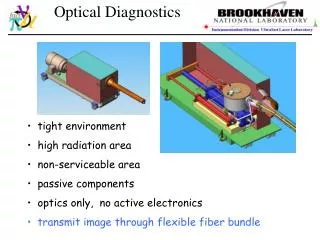
Laser Neutralization of H- detector • Photodissociation for H- ions is 0.75eV • Photons with λ<1500 nm can separate H- ion into free electron and neutral H • Deflect and detect low energy electrons Radius ~ 4” H- laser • Used at Los Alamos for transverse and longitudinal emittancemeasurements • Routinely used in SNS for measurement of transverse beam profiles • Challenge: reproduce this setup at multiple stations along the linac. • Solution: fiber distribution of laser signal. Photodissociation x-section
Overall layout integrating sphere power monitor • Narrow band lockin amp detects 1MHz modulated signal • Laser reprate is locked to 325MHz from machine • Galvo scan is triggered by macropulse event signal • Upper components are in tunnel, lower are in a laser hutch H- e- Faraday cup transimpedance preamp galvo fiber coax amplitude modulator lockin amp mod 1MHz MLL laser timing control lock box control, analysis
Commercial 10ps, 10W, 325MHz laser • Modelocked laser with internal amplifier • Sealed laser head, turn key • Pulse widths can be longer than 10ps, fixed at factory • Sync to RF option • Our laser is basically the same, without amplifier
Distribution to multiple stations 400m (approximate size of facility) • Loss will be 10dB or less through 100m fibers • Alternative is more lasers of lower power, but it’s $99k for 10W, $84k for 0.8W • No problem with solid fiber, <1dB 100m 100m 100m 100m laser laser laser precision rotation stage directs beam to any of 8 outputs by “go to position” command hollow fiber solid fiber pre-aligned collimators on X-Y and tilt stages
Summary • Time • Present:Femtosecond timing distribution has demonstrated <10 fsec over few km. Future: Demonstrate <1 fsec and 20 km. • Present: EO sampling techniques can measure electron signals with 10 THz bandwidths. Arrival times w.r.t clock at <10 fsec. Internet communication technology quite relevant. • Future: Demonstrate <1 fsec. • Intensity • Present: Laser stripping principle demonstrated. IR laser systems capable of ~100% stripping to be demonstrated in the next year. • Future: UV laser systems under development • Present: Concepts for fiber delivery of laser wires are developed. • Future: Demonstrate concept on prototype H- beam.