Download
1 / 24
240 likes | 434 Views
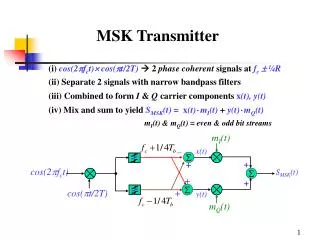
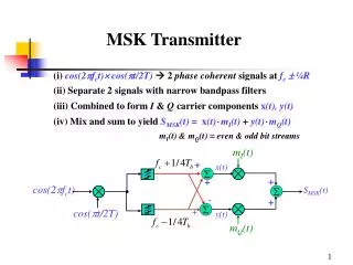
T. Sowlati, D. Rozenblit, R. Pullela, M. Damgaard, E. McCarthy, D. Koh, D. Ripley, F. Balteanu, I. Gheorghe. Polar Loop Transmitter. Content. Introduction Architectures for EDGE Transmitter Polar Loop Transmitter Measurement results Conclusion. GMSK. EDGE. Q. Q. I. I. Introduction.

E N D
T. Sowlati, D. Rozenblit, R. Pullela, M. Damgaard, E. McCarthy, D. Koh, D. Ripley, F. Balteanu, I. Gheorghe Polar Loop Transmitter
Content • Introduction • Architectures for EDGE Transmitter • Polar Loop Transmitter • Measurement results • Conclusion
GMSK EDGE Q Q I I Introduction EDGE modulation • 8-PSK with Gaussian filtering • Data rate 3X compared to GMSK • Spectrum very similar to GMSK • 17 dB amplitude variation 0 2 -10 0 -20 -2 -54dBc -30 -4 Power [dB] Power [dB] -60dBc -40 -6 -50 -8 -60 -10 -12 -70 -14 -80 -600 -400 -200 0 200 400 600 1000 1050 1100 1150 1200 1250 1300 Frequency [kHz] Time [us]
Introduction (ii) 0 • Unlike GMSK, EDGE cannot use nonlinear PA • For EDGE, PA operating point should be ~ 6dB bellow 1dB compression point. • This operating point provides only 3dB margin on Spectral Mask • Low Efficiency PA! -10 -20 Failure -30 -40 Power [dB] -50 Spectral failure due to Compression & AM-to-PM of 0.8°/dB -60 -70 -80 -600 -400 -200 0 200 400 600 Frequency [kHz] Motivation for our GSM / GPRS / EDGE Transmitter • Preserve high efficiency of the TX chain in GMSK mode • No SAW Filter in TX chain • No mode change in PA between GMSK & EDGE • Improve system efficiency in EDGE
2) Direct up conversion with IQ vector modulator 1) Superhet up conversion with IQ vector modulator SAW Filter • Well known techniques with simple interface between Transceiver and PA • Low Efficiency Linear PA for EDGE mode • External Filter to meet noise in RX band • Isolator to maintain EVM under VSWR • Tend to be expensive and bulky solutions 3) Polar modulator prior to the PA Isolator Driver PA PLL VCO SD D/A Modulator Digital Digital Amplitude Phase Modulator TX Architectures with Linear PA
Polar with open loop PA amplitude modulation • Very high PA efficiency is possible • Requires linear amplitude control • Sensitive to AM-to-PM in PA • Sensitive to load variations, temperature, supply • Requires isolator after PA to maintain EVM under VSWR • Accurate alignment of AM and PM components is very critical • Dynamic range for power control and power ramping is an issue • Required amplitude control range: • DCS / PCS > 50 dB • GSM 850/900 >48 dB
Polar Loop Transmitter • Very high PA efficiency is possible • Phase and amplitude feedback from PA output • Insensitive to AM-to-PM in PA • Insensitive to load variations, temperature, supply, etc. • No isolator required to maintain good EVM under VSWR • No pre- or post-PA filtering required to meet TX Noise in RX band Main Challenges: • Stability • Noise
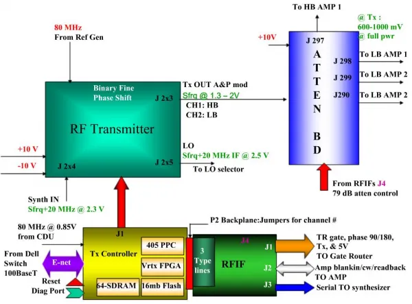
Polar Loop Transmitter Block Diagram • Closed Loop Power Control • High Linearity: IM3 < -40dBc • Wide Control Range > 65dB • Constant Gain over Control Range • Low AM-PM • Low Noise
Characteristics of AM / PM loops • Dominant poles / zeros are set by external components • Variations in loop bandwidth are mostly due to gain variations • Loop BW ↑ : Design Tolerance↑ • Loop BW ↓ : Noise ↓
System Simulations AM Loop gain (dB) PM Loop BW (Normalized) • Polar Loop Transmitter modeled and simulated using MATLAB, MATHCAD and ADS • EVM is not sensitive to mismatch between AM / PM Loops • Spectral mask degrades due to mismatch between loops Spectral Mask at 400kHz Offset (-dBc)
Power Amplifier - EDGE Specific requirements • Same GaAs die as GSM PA. • No Mode Select between GMSK / EDGE. • Modified Local Power Controller: • Linear Gain Control • Wide Bandwidth Gain Control • Low Noise • No Efficiency Degradation
PA Module 8 mm x 10 mm Transceiver: 5 mm x 4 mm PA Controller 2 mm x 2 mm Process Info & Die Photos • BiCMOS Process: Transceiver / PA Controller 30GHz Ft NPN, 0.35 mm CMOS, 3-layer metal • GaAs HBT Process: PA 25GHz Ft, 2 mm Feature size, 2-layer gold metal
PA Module Transceiver PA Controller Quad Band GSM / GPRS / EDGE RF Subsystem • Transceiver: • RX = 40mA GSM; 50mA DCS • TX = 85mA • SYNTH = 35mA • PA Controller • TX = 50mA • PA Module – Typical performance Low Band • GSM @ 34.5 dBm = 54% • EDGE @ 28.5 dBm = 35% High Band • GSM @ 31.5 dBm = 45% • EDGE @ 27.5 dBm = 35% Quad Band Evaluation Board
935 MHz 960 MHz 914.8MHz -79dBm 5dB/div TX Noise in RX Band: Highest Channel & Highest Power Level
Performance under VSWR Requirements: • 3:1 - EVM meet spec, RF spectrum allowed to fail spec • 6:1 - Maintain the link, EVM and RF spectrum allowed to be corrupted • 10:1 - No device damage Measured power at Antenna under VSWR
Spectral Mask at 400KHz Offset EVM under VSWR Variation Spec Spec Spectral Mask at 600KHz Offset Spec VSWR Measurement EDGE Mode Without Isolator: • No degradation of EVM ! • Modulation spectrum within spec up to 4:1 VSWR
Conclusions • A new transmitter architecture has been presented. • Closed AM and PM feedback loops ensure very robust performance. • High PA efficiency by use of saturated operation. • No SAW filter needed to meet TX noise in RX band. • No need for Isolator to maintain good EVM under VSWR. • Meet or exceed all GSM requirements in Quad Band with both GMSK and EDGE modulated signals.