Download

1 / 47
530 likes | 956 Views
Continuous-Time System Analysis Using The Laplace Transform. Dr. Mohamed Bingabr University of Central Oklahoma Slides For Lathi’s Textbook Provided by Dr. Peter Cheung. Outline. Introduction Properties of Laplace Transform Solution of Differential Equations

E N D
Continuous-Time System Analysis Using The Laplace Transform Dr. Mohamed Bingabr University of Central Oklahoma Slides For Lathi’s Textbook Provided by Dr. Peter Cheung
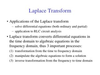
Outline • Introduction • Properties of Laplace Transform • Solution of Differential Equations • Analysis of Electrical Networks • Block Diagrams and System Realization • Frequency Response of an LTIC System • Filter Design by Placement of Poles and Zeros of H(s) The materials in these slides are covered in the Lathi Textbook all Ch 4 except sections 4.4, 4.7, 4.9, 4.11
LT x(t) = 3e-5t |X(s)| Omega Sigma
dv = dx u = e-st
HW5_Ch4: 4.1-1 (a, b, c, d), 4.1-3 (a, b, c, d, f), 4.2-1 (a, b, e, g), 4.2-3 (a,c), 4.2-6
Example In the circuit, the switch is in the closed position for a long time before t=0, when it is opened instantaneously. Find the inductor current y(t) for t 0. 2 1 H y(t) x(t) 5 0.2 F 10 V t=0
Example Find the response y(t) of an LTIC system described by the equation if the input x(t) = 3e-5tu(t) and all the initial conditions are zero; that is the system is in the zero state (relaxed). Answer :
Internal Stability • Internal Stability (Asymptotic) • If and only if all the poles are in the LHP • Unstable if, and only if, one or both of the following conditions exist: • At least one pole is in the RHP • There are repeated poles on the imaginary axis • Marginally stable if, and only if, there are no poles in the RHP, and there are some unrepeated poles on the imaginary axis.
External Stability BIBO The transfer function H(s) can only indicate the external stability of the system BIBO. BIBO stable if M N and all poles are in the LHP Example Is the system below BIBO and asymptotically (internally) stable? y(t) x(t)
System Realization • Realization is a synthesis problem, so there is no unique way of realizing a system. • A common realization of H(s) is using • Integrator • Scalar multiplier • Adders
Direct Form I Realization Divide every term by s with the highest order s3 H1(s) H2(s) X(s) W(s) Y(s)
H2(s) H1(s) X(s) W(s) Y(s) Direct Form I Realization
H1(s) H2(s) X(s) W(s) Y(s) Direct Form II Realization
Example Find the canonic direct form realization of the following transfer functions:
Cascade and Parallel Realizations Cascade Realization Parallel Realization The complex poles in H(s) should be realized as a second-order system.
Example Use Op-Amp circuits to realize the canonic direct form of the transfer function HW6_Ch4: 4.3-1 (b,c), 4.3-2 (b,c), 4.3-4, 4.3-7, 4.3-10, 4.4-1, 4.5-2, 4.6-1