Download
1 / 9
90 likes | 228 Views
Horn Alignment Cross-hair System. NuMI Horn Alignment Cross-hairs Target Hall Instrumentation Review November 18, 2002 David Ayres Argonne National Laboratory WBS 1.1.2 co-Manager. Outline Description, specifications Status and remaining work Summary. Cross-hair Alignment System.

E N D
Horn Alignment Cross-hair System NuMI Horn Alignment Cross-hairs Target Hall Instrumentation Review November 18, 2002 David Ayres Argonne National Laboratory WBS 1.1.2 co-Manager • Outline • Description, specifications • Status and remaining work • Summary
Cross-hair Alignment System • The cross hairs are three sets of horizontal and vertical strips of aluminum attached to the ends of Horn 1 and Horn 2 • Horizontal and vertical scans are performed with the low intensity proton beam across each set of cross hairs (target/baffle out) • Protons scattered by cross hairs are detected by Beam Loss Monitors (BLMs) downstream of Horns 1 and 2 • BLMs read out through ACNET • BLMs offset from beam centerline by 30 cm to avoid damage during high intensity running • Each set of cross hairs is offset from beam centerline by +2.5 mm or –2.5 mm, both horizontally and vertically • To distinguish the signals from different sets during scans • To avoid damage by high intensity beam • The upstream end of Horn 1 cannot have cross hairs but its location will be determined by scanning the neck of the horn inner conductor
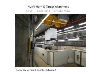
Target/Baffle/Horn-1 Cross-hair Geometry Stripline Target/Baffle Module Horn 1 Module Horn 1 Baffle Carrier Target Water tank BLM #1 Target and Baffle move out of beam for cross-hair scan Cross hair #1 Horn 1 neck
Cross-hair System Simulations • MARS beam heating calculations determined that cross hairs made of 1-mm wide aluminum strips would not overheat during full intensity running • NuMI-882, Byron Lundberg • GEANT simulations determined the thicknesses of cross hairs needed to give good scan signal-to-noise (0.6-0.8) in BLMs: #1 and #3 are 12 mm thick, #2 is 36 mm thick • NuMI-864, Debbie Harris • The NuMI-864 GEANT simulation also showed that • A scan of the Horn 1 neck gives exellent signal-to-noise (>10) • During normal running, cross hair scattering causes less than 0.2% changes in neutrino flux and in the ratio of near/far detector event rates
Cross-hair System Specifications • Proton beam instrumentation and control should permit scans at low intensity (1012 protons/pulse), 3.5 mm at cross hairs, 12 mm at Horn 1 neck. • Beam scans should determine Horn 1 and Horn 2 transverse locations to at least 0.5 mm and 1.0 mm respectively. • BLM response should be stable and sensitive to rate changes of ~5% at intensities expected during scans (107 particles/cm2/1012 protons/spill). • Additional material in the beam (beyond that assumed in NuMI-864) will degrade signal-to-noise ratio in scans. • Cross-hair material should not effect neutrino flux significantly (<1%). • Cross-hair and BLM locations, materials are chosen to ensure survival during full intensity beam running. • BLMs should be able to measure beam-pulse timing and targeting efficiency as a backup for target Budal monitor (after initial calibration against Budal monitor).
Cost and Schedule • The cross-hair task is approximately on schedule • The cost estimate (CR #156, Feb. 2002) still seems OK
Status and Remaining Work • Complete engineering of cross-hair mechanical structures • Complete engineering design and drawings • Repeat simulations with final cross-hair and BLM configurations and locations • Recheck calculation of beam heating with final geometry • Build and test prototype cross hair sets • Check mechanical stability during pulsing on Horn 2 in MI-8 during Spring 2003 • Test Horn 1 cross hairs in MI-8 during Summer 2003 • Build and install three production sets of cross hairs
Summary • Cross-hair and BLM designs are advanced enough to ensure that specifications are easily met • We have a practical plan for completing the engineering, prototyping, testing and construction of the cross-hair system on time and on budget • BLMs may provide partial backup for Budal monitor functions after beam commissioning