Download
1 / 14
140 likes | 145 Views
This article discusses the planning and strategy for testing future lepton colliders, including the baseline testing of the ILC Linac, system evaluations, and cost containment. The article also explores different approaches to power distribution and cavity pairing methodology.

E N D
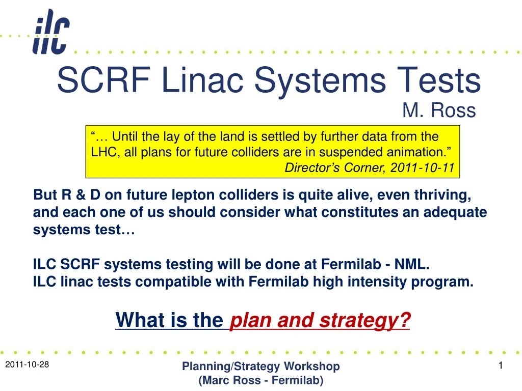
“… Until the lay of the land is settled by further data from the LHC, all plans for future colliders are in suspended animation.” Director’s Corner, 2011-10-11 SCRF Linac Systems Tests But R & D on future lepton colliders is quite alive, even thriving, and each one of us should consider what constitutes an adequate systems test… ILC SCRF systems testing will be done at Fermilab - NML. ILC linac tests compatible with Fermilab high intensity program. What is the plan and strategy? M. Ross Planning/Strategy Workshop (Marc Ross - Fermilab)
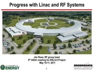
GeV-class pulsed linacs based on TESLA technology: Planning/Strategy Workshop (Marc Ross - Fermilab) • TTF (2001) 250 MeV; 17 cavities • Demonstrated full current, stable acceleration • SNS (2006) 1 GeV; 81 cavities • 98% SC linac availability • FLASH (2005) 1.2 GeV; 56 cavities • 9 mA demonstrations (2008 -) • KEK-STF (2013 -) ~ 16 cavities • NML (2012 -) ~ 48 high gradient cavities • EU-XFEL (2014) - 800 cavities
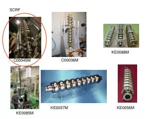
ILC Linac • Cost Drivers: • Gradient • Cryogenics • Electricity/Cooling • RF Power Source/ Distribution • Pre-installation CM Testing HLRF=High Level RF CM=CryoModule Linac to provide 250 GeV mono-energetic, long-term stable, high power beams, reliably, with minimum cost. Components: HLRF Source Power Distribution Cavity/CM “Beam” Controls Utilities
ILC Linac Baseline Testing: Planning/Strategy Workshop (Marc Ross - Fermilab) • TWO baseline High Level RF options: • To best suit site topography • Both require system tests • Third option: RDR Backup • Gradient, RF Power, Utility, Cryogenic, linac length and controls overhead margins to be specified and tested • Includes test of gradient ‘spread’ • Primary Goal of System Test COST • Cost contained by best-effort evaluation of baseline cost performancerelationship
Reference Linac Design - 2007 Planning/Strategy Workshop (Marc Ross - Fermilab) (Basis for NML)
KCS: 26 cavities powered from a single tap-off (similar to NML) DRFS: cavities powered in groups of 4 2009 Linac RF (KCS + DRFS): Planning/Strategy Workshop (Marc Ross - Fermilab)
Qext Fractional Size Input Power Reflected Power Gradient 31.5 MV/m Average 24.5 MV/m 29.8 MV/m 38.5 MV/m Flattop Operation with a Spread of Cavity Gradients cavity-by-cavity adjustable power and Q_l. Rise time is common to all cavities – Assumes flat distribution of limiting gradients 31.5 +/- 20% Most important slide +/- 20% spread allowed
ILC Linac Parameters: Planning/Strategy Workshop (Marc Ross - Fermilab)
56 Cavities; 7 cryomodules 3 Klystrons (power?) Gradient demonstration Cavity coupling (Q_l) control No individual cavity power control (P_k) FLASH: Primary ILC System Test Worse than ILC limit
Summary: System Test Objective: 2012 • Remaining topics: Linac engineering @ full gradient • Prove and Characterize Overhead ‘Margins’: • Gradient • Power • Cryogenic • Utility • Controls • Study (at nominal parameters): • Performance • Controls methodology • Failure rates / reliability • Degradation
Gradient: ‘Operational Margin’ Planning/Strategy Workshop (Marc Ross - Fermilab) • Lessons from existing linacs: • SNS: radiation - generated heating • Flash: controls strategy / implementation • Gradient Beam-Calibration – a very important benefit of FLASH • Performance may never better than in vertical test; except (possibly) through rinsing • Relationship between Practical (CM) and Intrinsic (VTS) cavity performance; • e.g. limits due to external constraints… quench, radiation, cryo load.
Power Distribution System • Folded Magic-T’s and Motorized U-Bend s for Each Cavity • remotely adjustable by pairs • no pair sorting required • circulators necessary • Original VTO (Variable Tap-Off) Pair-Feeding Concept • manually adjustable by pairs • requires pair sorting • circulators can be eliminated • Alternate Scheme w/ Folded Magic-T’s and Motorized U-Bend Phase Shifters • remotely adjustable by pairs • requires pair sorting • circulators can be eliminated Planning/Strategy Workshop (Marc Ross - Fermilab) • How to tailor power feed for each cavity • Cost effectiveness of: • Circulators • Power controls (mechanized) • Cavity pairing
Methodology for ramping to maximum gradient and full beam loading…? Julian Branlard Step 1 Step 3 Step 2 Cavity Voltages: 6mA Default Qexts, 3.5MW Cavity Voltages: 6mA Shin’s Qexts, 3.5MW Cavity Voltages: 6mA Shin’s Qexts, 5.1MW Fraction of quench limit Fraction of quench limit Fraction of quench limit Would be possible to do initial tests of methodology in RF-only mode at NML?