Download
1 / 45
450 likes | 589 Views
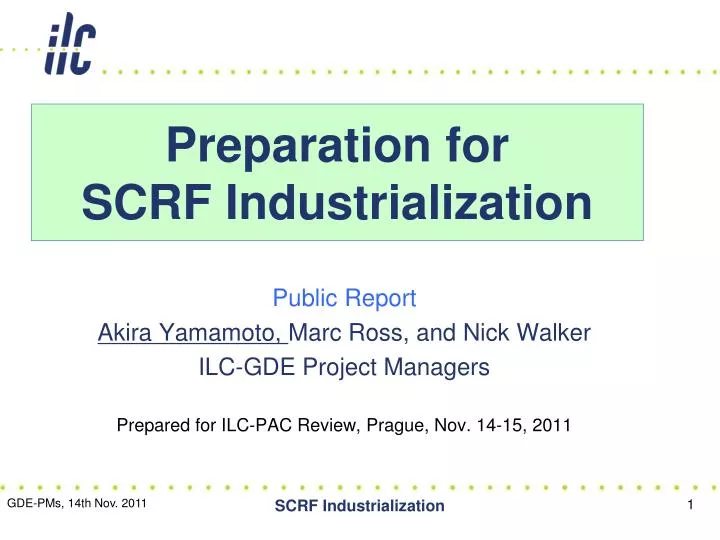
Preparation for SCRF Industrialization. Public Report Akira Yamamoto, Marc Ross, and Nick Walker ILC-GDE Project Managers Prepared for ILC-PAC Review, Prague, Nov. 14-15, 2011. Outline . Introduction Industrialization models Progress in Communication with industry

E N D
Preparation forSCRF Industrialization Public Report Akira Yamamoto, Marc Ross, and Nick Walker ILC-GDE Project Managers Prepared for ILC-PAC Review, Prague, Nov. 14-15, 2011 SCRF Industrialization
Outline • Introduction • Industrialization models • Progress in Communication with industry • Plan for further study SCRF Industrialization
SCRF-ML Technology Required RDRSB2009 SCRF Industrialization
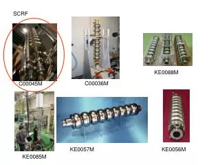
Cavity Fabrication Process Material/ Sub-component Cavity Fabrication HeTank Surface Process LHe-Tank Assembly Vertical Test = Cavity RF Test Cryomodule Assembly and RF Test SCRF Industrialization
SCRF Procurement/Manufacturing Model ILC Host-Lab Regional hub-laboratories responsible to regional procurements to be open for any world-wide industry participation Technical Coordination for Lab-Consortium Regional Hub-Lab: A Regional Hub-Lab: E, & … World-wide Industry responsible to ‘Build-to-Print’ manufacturing Regional Hub-Lab: D Regional Hub-Lab: B Regional Hub-Lab: C: responsible to Hosting System Test and Gradient Performance : Technical coordination link : Procurement link SCRF Industrialization
Production Process/Responsibility SCRF Industrialization
Reference for Cavity Specification • Technical guideline for ILC-GDE TDR and the cost estimate: • referring Specifications for E-XFEL SCRF 1.3 GHz Cavity, issued by DESY • EXFEL/001 and associated documents :Rev.B, June 2009, by courtesy of W. Singer (DESY-XFEL)), • The reference specification is available with ILC-GDE PMs, under permission of W. Singer (DESY-XFEL) • URL: http://ilcagenda.linearcollider.org/event/ILC-SCRF-TR Courtesy: W. Singer scrf-treq SCRF Industrialization
Technical Specification Example for Nb Sheet • Electrical Properties • RRR: > 300 • Chemical contents • see table • Microstructure • Re-crystalized 100 % • Grain-size: ASTM 6 or finer • Local grain size: ASTM 4-5 • Mechanical Properties • Ultimate strength: > 140 N/mm2, RT • Yield strength: TBD (> xx N/mm2, RT) • Elogation; > 30 % • Hardness: ≤ 60 • Shape/size: TBD • Rect. Sheet : ~ 300 mm sq. or • Circular sheet: ~280 mm dia. with a center-hole • Possibility of Blanking (in consortium: to be discussed) • Thickness : 2.8 mm +/- 0.1 mm • Flatness: 2 % or better • Surface roughness: < 15 mm (RF side) SCRF Industrialization
Cavity Deliverable assuming EXFEL cavity specification Courtesy: W. Singer • From EXFEL specification: 02L BQM-Cavity in He Tank SCRF Industrialization
Cavity with plug-compatibility Important for Global Cooperation Plug-compatible interface need to be established SCRF Industrialization
Blade and Slide-Jack Tuners SCRF Industrialization
Outline • Introduction • Progress in Communication with industry • Progress since May 2011 and status • Plan for further study SCRF Industrialization
SCRF Industrialization Study • Our efforts: • Understand status of industry, and discuss technology and the cost saving effort for the ILC scale production • Study the ILC SCRF industrialization models • Two approaches in 2011~: • Visiting and communication with potential industry • visit industry and discuss ‘request for information’ for cost-study, with currently available industrial technology • Study on specific subjects with small-contracts • Possible Factory layout for cavity production (in AS; KEK centered) • System engineering for mass production (in EU; CERN centered) • The coordination meeting held at CERN, in May, July, Sept., 2011 • Mass production technology study prepared (in AMs; Fermilab centered) SCRF Industrialization
Communication with Industry in 2011 • Visit factories, and Request for information • Based on currently available manufacturing technology and available information with worldwide industry • Assume the EXFEL ‘build-to-print’ specifications as a common reference, and • Allow alternate designs with ‘plug-compativility’ and with the equivalent or lestt cost and/or with better performance • Requests for information to companies • Cost comparisons: 20/50/100 % in3 / 6 year after 2-year preparation ? • Factory-site location: company or laboratory ? • Sharing responsibilities for the cost-effective production ? • Deliverables with ‘build-to-print’ fabrication? • Consortium to be considered or not SCRF Industrialization
Material Cost-study compared with RDR & EXFEL (updated: Nov., 2011) Note: The aboveILC material cost is 9-cell cavity’s central part only, Total SC material cost including end-group need to be ~ 10 % higher We assume the material cost : 20 x (1+0.1) = 22 K ILCU Including the QA/QC cost of “ 2 ”, the total material cost : >>> 22+2 = 24 k-ILCU SCRF Industrialization
Cavity Cost-study compared w/ RDR and EXFEL (updated, Nov., 2011)
Updated Cavity Cost-study compared with RDR and E-FXEL (as of Oct., 2011) Confidential • Further mass production cost study with contracts in progress: • RI-DESY: 50, 100 % production cost including facility cost • AES-FNAL: 20 % (& more as option) facility investment cost • MHI-KEK: 50, 100 % production cost w/ facility cost • To be completed by spring, 2012.
Outline • Introduction • Progress in Communication with industry • Plan for further study • Evaluation of technical input • Further detail cost studies with regional efforts through key laboratories, SCRF Industrialization
Plan for Further Work • Evaluation of the industrial response • Frame and common format suggested for smooth comparisons. • Cost estimate process and conditions: • Technical survey and investigation for cost-effective production • Model dependent cost comparison (20~100%) to be further quantitatively evaluated • Hub laboratory’s input inevitable specially for cryomodule assembly and cold test • Project management scope how global cooperation and sharing the production to be taken into account • More mutual work with cost-engineers inevitable SCRF Industrialization
Technical Information Received • To be carefully • evaluated, • in cooperation of • PMs and Cost-engineers SCRF Industrialization
Further Plans to prepare TDR • Cost-estimate work for TDR (by April, 2012) • Communication with industry under contract • Cavity: RI (w/ DESY), AES (w/ Fermilab), MHI (w/ KEK), • Cryomodule Assembly: BN (w/ CERN), Hitachi (w/ KEK), • Quadrupole: Toshiba (Q, w/KEK) • HLRF (SLAC, KEK) • Communication with laboratories • Fermilab, JLab, CERN, DESY, Saclay, INFN, KEK, … • Technical specification to be fixed for TDR cost • SCRF meeting at IHEP, Dec. 8-9, 2011 • SCRF-TBR, Jan. 19-20, 2011 • GDE meeting, 23-26, April SCRF Industrialization
Technical Issues toward TDR • Cavity gradient : • Update and fix the cavity production and process recipe. • Update and fix the successful production yield definition in production stage, • including new parameters such as radiation, and the process w/ tumbling • Gradient spread of 31.5 MV/m +/-20 %, with sorting method, • Gradient degradation after assembly into the cryomodule (see: HLRF/DRFS w/ circulator) • Cavity Integration • A baseline design chosen for the TDR cost-estimate base, • Including selection of tuner, coupler, beam-flange, magnetic shield, and LHe tank • Plug-compatible design to be allowed in case of cost equivalent or more cost effective. • Cavity delivery condition with LHe-tank, and cold-test sequence/monitor, • Cryomodule and Cavity-string Assembly • Cryomodule string configuration with 8 + (4+Q+4) + 8 cavity-string assembly • Simplification of 5K radiation-shield: simplification of bottom, and removal at inter-connect. • Split-yoke, conduction-cooled quadrupoles • Efficient alignment • Cavityand Cryomodule Test • Warm conditioning of Input Coupler: before or after installation into the tunnel • Cold performance test: How much fraction to be cold tested? Subjects to be tested? SCRF Industrialization
Demonstrationsand Evaluation of Various Couplers and Tuners in S1-Global • Every coupler and tuner demonstrated, as expected, and be applicable for ILC cavities • Finding various subjects to be further investigated and settled SCRF Industrialization
Continued • Cryogenics • Location and the options (reducing the number of station) of cryogenic systems, • Capacity optimization and heat balance with cryomodule heat-load • HLRF • KCS/DRFS/RDR-unit HLRF system configuration including backup power supplyand utilities with the single tunnel design • Marx generator to be a baseline modulator, • AC power capacity optimization with gradient spreads, • Adaptability against cavity degradation after installation into cryomodule, by using circulator and power distribution system, • Optimizations for low-power and high-power option. • Tunable power distbribution system • ML Integration • Beam dynamics • Quadrupole/BPM periodicity, locations, alignment, and beam tunability, • Bunch spacing limit specially on KCS (requirement of DR beam dynamics) • Availability, reliability, and backup of cryomodules to be required SCRF Industrialization
How to prepare for TDR? • Discussion during LCWS • Further technical discussion in TTC, Dec. 5 - 8 • ILC Specific discussion in post-TTC, Dec. 8-9, • Consensus for TDR writing, BTR at KEK, Jan. 19 – 20, 2012 SCRF Industrialization
Summary • Cost-study in Communication with industry • Major companies responded to our ‘request for information’, and we have received costing information. • More effort required to reduce the mass production cost, • We are in progress to communicate with industry , • to figure out production scale and cost-effective facility (recent reports attached), • to prepare for the information on the model dependent cost estimates (20 ~ 100 %). • Further study required on risk-mitigation in the various models. • Cost study in Communication with Laboratories • Communication with potential regional hub-laboratories will be important to establish a whole scope of the cryomodule assembly/test. • DESY, Fermilab, and KEK are working to understand more mass production with globally distributed production and/or single facility prodcution, • CERN’s involvement is very important to figure out a lab-hosting cryomodule assembly and test models, in contract with industry SCRF Industrialization
Backup Slides • Reference information to establish baseline design for the TDR cost estimates SCRF Industrialization
Required Production in ILC 9-cell cavities: ~ 18,000 (17,325) production Cryomodule: ~2,000 (1,824) production Pre-production 2 years + Full production 6 years SCRF Industrialization
Standard Procedure Establishedfor ILC-SCRF Cavity evaluation, in guidance of TTC • Key Process • Fabrication • Material • EBW • Shape • Process • Electro-Polishing • Ethanol Rinsing or • Ultra sonic. + Detergent Rins. • High Pr. Pure Water cleaning allow twice SCRF Industrialization
D. Kostin & E. Kako Cryomodule Gradient Spread and Degradation Observed at DESY and KEK, as of Nov. 2010 • FLASH: • 3 PXFEL cryomodules • ILC R&D: • S1-Global cryomodule • CM1 (S1-Local @ Fermilab) • Current status: • 12/40 degraded with ~ 20 % PXFEL-1 PXFEL-2 PFEL-3 S1-Global SCRF Industrialization
Current statistics on cavity gradient degradation • Statistics, available now (see right table) • Rate of degradation with > ~ 20 % • ~12/40, which leads to ~30%. This is too high, and efforts of improving is required. How improved? Maybe up to ~10%.(acceptable?) • Sorting after vertical test is planed in DRFS. Furthermore 10% decrease of gradient is likely occurred and this reality should included at the construction plan.This effect also results in cost-up. • Numbers of cavities and rf units must be increased if total acceleration is short and it is not compensated by the overhead. • Since DRFS employs one rf unit feeds powers to 2 or 4 cavities without using circulator, and therefore cavity gradient sorting is inevitable, effect of unexpected cavity gradient degradation is larger than other scheme such as RDR and KCS. Operational experiences SCRF Industrialization
Estimate assuming 1/10 cavities degraded with 20 % • Simple Calculation • 80 % pairs with full performance and 20 % pairs with 0.8 x full performance • 0.8 x 1 + 0.2 x 0.8 = 0.96 without circulators, • 0.8 x 1 + 0.2 x {(1 +0.8)/2} = 0.98 with circulators, • Difference to be 0.02 = 2 % of {Cavity+HLRF} cost required to add/compensate this degradation, • Necessary study • Full circulator + distributors cost to be evaluated in comparison with the additional cryomodule backup cost (additional extension of linac). • Operational flexibility and better efficiency by circulators and power distributors to be evaluated SCRF Industrialization
Cavity Deliverable assuming EXFEL cavity specification Courtesy: W. Singer • From EXFEL specification: 02L BQM-Cavity in He Tank SCRF Industrialization
EXFEL Cavity and Tuner SCRF Industrialization
S1-Global Assembly/Test with Global Effort DESY, Sept. 2010 DESY, FNAL, Jan., 2010 FNAL & INFN, July, 2010 INFN and FNAL Feb. 2010 March, 2010 DESY, May, 2010 June, 2010 ~ SCRF Industrialization
Comparison of cavity performance ave. Eacc,max VT : 30 MV/m 1 cav : 27 MV/m 7 cav : 26 MV/m C D D AES004 ACC011 Z108 Z109 MHI-05 MHI-07 D : Detune C : Coupler MHI-06 MHI-09 FNAL DESY KEK SCRF Industrialization Performance reduction in two cavities and one coupler Tuner mechanics trouble in two cavities
7-cavity operation by digital LLRF LLRF stability study with 7 cavities operation at 25MV/m Stability in 6300 sec. Field Waveform of each cavity vector-sum gradient amplitude stability in pulse flat-top phase stability in pulse flat-top - Vector-sum stability: 24.995MV/m ~ 24.988MV/m (~0.03%) - Amplitude stability in pulse flat-top: < 60ppm=0.006%rms - Phase stability in pulse flat-top: < 0.0017 degree.rms SCRF Industrialization
A Proposal Revised 9 4 + Q +4 9 • Keep the concept of 8 cavity sting unit, to be simplified • Accept two typs of Cryomodules (from Cryomodule manufacturing) 8 8 Q 8 8 4 + Q +4 8 SCRF Industrialization
Quadrupole Cross-Section LHe tank for current leads connections Beam pipe Iron yoke SCRF Industrialization V. Kashikhin, FNAL Review, March 2, 2010
R&D/Demonstration Required • Rapid response to beam handling • Study by K. Kubo and K. Yokoya • R&D cooperation under discussion between Fermilab and KEK • Magnet by Fermilaband Conduction cooling by KEK SCRF Industrialization
Access Routes with Mountain-site SCRF Industrialization
Layout of 2K Cryoplants ML BDS IP RDR-based How about this? 2K Cryoplants SCRF Industrialization
High-Level RF Solutions 2×35 10MW MB klystrons Klystron Cluster Scheme, KCS (SLAC) Distributed RF Sources, DRFS (KEK) ~4000×800kW klystrons SCRF Industrialization