Download
1 / 32
370 likes | 699 Views
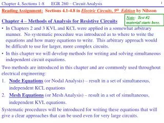
Chapter 4 Methods of Analysis of Resistive Circuits. Resistive Circuit Analysis.

E N D
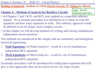
Resistive Circuit Analysis • Node voltage analysis - with independent source : current source / voltage source - with dependent source• Mesh current analysis- with independent source : voltage source / current source- with dependent source
Node Voltage Analysis – with current sources Figure 4.2-1(a) A circuit with three nodes.(b) The circuit after the nodes have been labeled and a reference node has been selected and marked.(c) Using voltmeters to measure the node voltages. To write a set of node equations, we do two things:1. Express element currents as functions of the node voltages.2. Apply KCL at each of the nodes of the circuits, except for the reference node.
Node Voltage Analysis – with current sources Figure 4.2-2Node voltages, v1 and v2 , and element voltage, va, of a circuit element. Figure 4.2-3 Node voltages, v1 and v2, and element voltage, v1 -v2, of a (a) generic circuit element, (b) voltage source, and (c) resistor.
Node Voltage Analysis – with current sources Figure 4.2-4(a) A circuit with three resistors.(b) The resistor voltages expressed as functions of the node voltages.(c) The resistor currents expressed as functions of the node voltages. node (a) If KCL node (b)
Node Voltage Analysis – with current sources Example 4.2-1 node (a) node (b)
Node Voltage Analysis – with current sources Example 4.2-2 Example 4.2-3 node (a) node (b) node (c)
Node Voltage Analysis – with current sources Exercise 4.2-1 Exercise 4.2-2 node (a) node (b)
Node Voltage Analysis – with current and voltage sources Figure 4.3-1Circuit with an independent voltage sourceand an independent current sources. Figure 4.3-2Circuit with a supernode that incorporate va and vb. A supernode consists of two nodes connected by an independentor a dependent voltage source
Node Voltage Analysis – with current and voltage sources Example 4.3-1 Method #1 Method #2 Apply KCL to the Supernode Example 4.3-2 Method #1 Method #2 : apply KCL to the Supernode
Node Voltage Analysis – with current and voltage sources Example 4.3-3 Let Supernode be the 10V source Apply KCL to the Supernode Exercise 4.3-1 Exercise 4.3-2
Node Voltage Analysis – with dependent sources Example 4.4-1 KCL at node (b) Example 4.4-2 KCL at supernode Example 4.4-3 KCL at node (a) KCL at node (b)
Node Voltage Analysis – with dependent sources Exercise 4.4-1 KCL at node (a) Exercise 4.4-2
Mesh Current Analysis – with independent voltage source Figure 4.5-1Nonplanar circuit with a crossover. - Loop- Mesh : 다른 loop를 포함하고 있지 않은 loop (cross over가 없는 circuit에만 적용 가능) Figure 4.5-2Circuit with four meshes.Each mesh is identified by dashed lines.
Mesh Current Analysis – with independent voltage source Figure 4.5-3(a) A circuit with two meshes(b) Inserting ammeters to measure the mesh currents. Figure 4.5-4 Mesh currents, i1 and i2,and element current, i1 – i2, of a(a) generic circuit element,(b) current source, and (c) resistor. To write a set of mesh equations, we do two things:1. Express element voltages as functions of the mesh currents.2. Apply KVL to each of the meshes of the circuits.
Mesh Current Analysis – with independent voltage source Figure 4.5-5 Mesh #1 Mesh #2 Mesh #1 Mesh #2 Figure 4.5-6 Mesh #3
Mesh Current Analysis – with two independent voltage sources Exercise 4.5-1
Mesh Current Analysis – with current and voltage source Figure 4.6-2Circuit with an independent current sourcecommon to both meshes. Mesh #1 Figure 4.6-1 Circuit with an independent voltage source and an independent current source. Mesh #1 Mesh #2
A Supermesh is one larger mesh created from two meshes that have an independent or dependent current source in common. Mesh Current Analysis – with current and voltage source Figure 4.6-4 Circuit with a supermesh that incorporates mesh 1 and mesh 2, indicated by the dashed line. Example 4.6-1 Mesh #2 Mesh #3 Supermesh Mesh #3 Supermesh Mesh #3 Current source
Mesh Current Analysis – with current and voltage source Example 4.6-2 Method #1 Method #2
Mesh Current Analysis – with current and voltage source Exercise 4.6-1 Exercise 4.6-2
Mesh Current Analysis – with dependent source Example 4.7-1 KVL to mesh #1 KVL to mesh #2
Mesh Current Analysis – with dependent source Example 4.7-2 KVL to mesh #1 KVL to mesh #2
Node Voltage & Mesh Current Analysis – comparison Figure 4.8-1 Example 4.8-1 KVL to mesh #3 Figure 4.8-2
Node Voltage & Mesh Current Analysis – comparison Figure 4.8-4 Example 4.8-2 Figure 4.8-3 KCL at node 3
NodeVoltage and Mesh Current Analysis – PSpice Example 4.10-1
NodeVoltage and Mesh Current Analysis – MATLAB Example 4.11-1 Example 4.11-2
Potentiometer Angle Display Figure 4.12-1Proposed circuit for measuring and displaying the angular position of the potentiometer shaft. where Angle varies from to Potentiometer varies from to Figure 4.12-3 The redrawn circuit showing the mode v1. Figure 4.12-2Circuit diagram containing models of the power supplies, voltmeter, and potentiometer.
Potentiometer Angle Display Figure 4.12-3 The redrawn circuit showing the mode v1. Assumption Then, Let
Potentiometer Angle Display Figure 4.12-4 The final designed circuit. Suppose
Homework #4 Problems P4.2-4 / P4.2-7 / P4.3-5 / P4.3-11 / P4.4-7 / P4.4-10 / P4.4-17 / P4.5-6 / P4.6-10 / P4.7-10 / P4.8-2