Download
1 / 26
260 likes | 424 Views
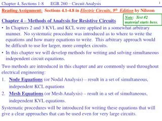
Chapter 4, Sections 1-8 EGR 260 – Circuit Analysis. 1. Reading Assignment: Sections 4.1-4.8 in Electric Circuits, 9 th Edition by Nilsson. Note : Test #2 material starts here. Chapter 4 – Methods of Analysis for Resistive Circuits

E N D
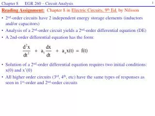
Chapter 4, Sections 1-8 EGR 260 – Circuit Analysis 1 Reading Assignment: Sections 4.1-4.8 in Electric Circuits, 9th Edition by Nilsson Note: Test #2 material starts here. • Chapter 4 – Methods of Analysis for Resistive Circuits • In Chapters 2 and 3 KVL and KCL were applied in a somewhat arbitrary manner. No systematic procedure was introduced as to where to write the equations and how many equations to write. This arbitrary approach would be difficult to use for larger, more complex circuits. • In this chapter we will develop methods for writing and solving simultaneous independent circuit equations. Two methods are introduced in this chapter and are commonly used throughout electrical engineering: 1. Node Equations (or Nodal Analysis) – result in a set of simultaneous, independent KCL equations 2. Mesh Equations (or Mesh Analysis) – result in a set of simultaneous, independent KVL equations. Systematic procedures will be introduced for writing these equations that will give a clear approaches that can be used even for very large circuits.
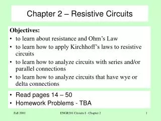
Chapter 4, Sections 1-8 EGR 260 – Circuit Analysis 2 Node Equations First, a couple of definitions: Ground ( or reference) – a node in the circuit used as a reference point for measuring node voltages. As far as node voltages are concerned, the ground node is the 0V point in the circuit. Ground symbols: Node voltage – the voltage at a node with respect to ground. For example, VA is the voltage at node A, meaning that the positive terminal is at A and the negative terminal is at the ground node. Note: Node voltages are relative measurements. The value of a node voltage changes if a different ground node is used.
Chapter 4, Sections 1-8 EGR 260 – Circuit Analysis 3 Illustration – The use of a ground essentially means that a common node will be used as the negative terminal for all voltages (node voltages) in the circuit. This would be like using a voltmeter to measure various voltages where the negative lead of the meter always stayed on the ground node and the positive lead then moved to various other nodes to measure “node voltages.” Case 2 – Using a voltmeter to measure node voltage VB Case 1 – Using a voltmeter to measure node voltage VA Note – In all cases the negative side of the meter is connected to the ground node in order to measure node voltages.
Chapter 4, Sections 1-8 EGR 260 – Circuit Analysis 4 Component Voltages Recall that node voltages are relative quantities. If a different reference is used, the node voltages change. Component voltages are not relative quantities. Component voltages can be determine from node voltages as illustrated below. Vx = VA - VB (prove that this is true for any ground C) C
Chapter 4, Sections 1-8 EGR 260 – Circuit Analysis Node B used as ground Node C used as ground Node D used as ground 5 Node A used as ground Voltage VA VB VC VD Vx = VA - VB • Example: The circuit below includes the value of the component voltages. • Determine the corresponding node voltages (fill out the table). • Show that Vx = VA - VB for each possible set of node voltages.
Chapter 4, Sections 1-8 EGR 260 – Circuit Analysis 6 • Node equations – Procedure • 1) Label each node. • 2) Select a node as the reference (or ground) node. • Note:It is generally easier to pick the ground adjacent to a voltage source. • 3) If the circuit has no voltage sources, skip to step 4. Otherwise: • A) For any voltage source or group of voltage sources adjacent to the ground, all node voltages adjacent to the sources can be determined so no KCL equation will be required. • B) For any voltage source or group of voltage sources not adjacent to the ground, a supernode is required (to be discussed later). • 4) Write a KCL equation at each node not adjacent to a voltage source and not at the ground node. (Also write a KCL equation for each supernode.) Express resistor currents in terms of node voltages. • 5) Solve the simultaneous KCL equations. In general, the number of equations required is: # Node Equations = #nodes - #voltage sources - 1
Chapter 4, Sections 1-8 EGR 260 – Circuit Analysis 7 _ V2 + 4 I1 2 8 4 A 2 A Example: Analyze the following circuit using node equations. Use the result to find I1, V2, and the power dissipated by the 8 ohm resistor.
Chapter 4, Sections 1-8 EGR 260 – Circuit Analysis 8 Example: Use node equations determine the current I. (Answer: I = 1.92 A.)
Chapter 4, Sections 1-8 EGR 260 – Circuit Analysis 9 Example: Use node equations determine the current I.
Chapter 4, Sections 1-8 EGR 260 – Circuit Analysis 10 6I1 40 5 I1 12 A 50 V 20 10 Circuits containing dependent sources Key: Replace the control variable in terms of node voltages. Example: Use node equations determine the current I1 .
Chapter 4, Sections 1-8 EGR 260 – Circuit Analysis 11 Supernodes A supernode is a node formed by drawing a surface around a voltage source or group of voltage sources that are not adjacent to the reference (this would be a node if the voltage sources in the supernode were set to zero or shorted). • When supernodes are used, node equations are written as follows: • Write a KCL equation at each node not adjacent to the reference or adjacent to a voltage source • Write one KCL equation for each supernode.
Chapter 4, Sections 1-8 EGR 260 – Circuit Analysis 12 • Illustration - Supernode: • Note that it is not possible to place the ground adjacent to both voltage sources in the circuit shown, so a supernode is necessary. • If the ground is placed at node D (adjacent to the 50V source) then a supernode is needed around the 20V source. • Note that the voltage difference between nodes A and B is 20V, so: Supernode relationship: VA - VB = 20 • Think of the supernode as the node that would exist if the voltage source were replaced by a short (a wire).
Chapter 4, Sections 1-8 EGR 260 – Circuit Analysis 13 Example: Analyze the circuit shown using node equations. Show that Pdel = Pabs .
Chapter 4, Sections 1-8 EGR 260 – Circuit Analysis 14 Example: Use node equations determine V and I. Is a supernode required?
Chapter 4, Sections 1-8 EGR 260 – Circuit Analysis 15 R8 R1 R1 R6 R7 R2 R2 V1 V1 R5 R5 R4 R4 R3 R3 R9 Mesh Equations Mesh equations (or mesh analysis) are a set of simultaneous KVL equations. Mesh equations have one restriction: Mesh analysis can only be used if a circuit is planar. A circuit is planar if it could be drawn on a 2D surface with no crossovers. Example: Is the following circuit planar? Example: Is the following circuit planar?
Chapter 4, Sections 1-8 EGR 260 – Circuit Analysis 16 Mesh – a minimal region in a circuit that is bounded by circuit elements. A more informal definition is that a mesh is like a window pane in a window. 4 window panes 4 meshes Circuit Window
Chapter 4, Sections 1-8 EGR 260 – Circuit Analysis 17 IA IB IC ID I3 R8 R9 I1 IA IB R10 R11 I2 R2 R7 IC R13 ID R12 V2 I4 Mesh current – a current associated with a mesh. Mesh currents are generally drawn all clockwise (CW) or all counter clockwise (CCW). Example: Mesh currents IA, IB, IC, and ID are shown in the circuit to the right. Component currents – note that a component current is made up of either one or two mesh currents. Example: Define the component currents I1, I2, I3, and I4 in terms of mesh currents. I1 = I2 = I3 = I4 =
Chapter 4, Sections 1-8 EGR 260 – Circuit Analysis 18 R8 R9 _ + R11 IA IB V3 V1 R10 _ + R2 R7 _ V2 + R13 R12 Vx IC ID Expressing resistor voltages in terms of mesh currents: Example: Define the resistor voltages V1, V2, and V3 in terms of mesh currents. V1 = V2 = V3 =
Chapter 4, Sections 1-8 EGR 260 – Circuit Analysis 19 Mesh Equations – Procedure: 1) Be sure that the circuit is planar (redraw it if necessary). 2) Label the mesh currents (generally all CW or all CCW). 3) If the circuit contains any current sources on the outer edge, the corresponding mesh currents are defined. If the circuit contains any internal current sources, a supermesh is required (more information later). 4) Write a KVL equation in each mesh with no current sources and one KVL equation around each supermesh. Express resistor voltages in terms of mesh currents (see below). 5) Solve the equations simultaneously. In general, the number of mesh equations is: # Mesh Equations = # meshes - # current sources
Chapter 4, Sections 1-8 EGR 260 – Circuit Analysis 20 Example: Use mesh equations to determine the current I. Note that this problem was analyzed in previous class using node equations and I was determined to be 1.92 A.
Chapter 4, Sections 1-8 EGR 260 – Circuit Analysis 21 Example: Use mesh equations to analyze the circuit shown below. Use the results to determine V1, V2, I3, and the power absorbed by the 80 ohm resistor.
Chapter 4, Sections 1-8 EGR 260 – Circuit Analysis 22 Dependent Sources: The key to using mesh analysis on circuits with dependent sources is to redefine the control variables in terms of mesh currents. Example: Use mesh equations to determine V1 and i1 in the circuit shown below.
Chapter 4, Sections 1-8 EGR 260 – Circuit Analysis 23 IA IB IC Supermesh If a circuit contains an internal current source, a supermesh is required in order to perform mesh analysis. A supermesh is the new, larger mesh that is created by removing the internal current source. A new mesh current is not added. The supermesh simply shows the path for a KVL equation around the supermesh. Example: 1)Note that the following circuit has an internal current source, so a supermesh is required.
Chapter 4, Sections 1-8 EGR 260 – Circuit Analysis 24 2) The supermesh is the new, larger mesh created by removing the current source (as shown on the following page). Supermesh IA IB IC 3) Note that the supermesh defines a path for a KVL equation. No new mesh current is defined. 4) Also note that the internal current source can be used to form a relationship between currents IB and IC. In general, this is referred to as the supermesh relationship. Supermesh relationship: IB - IC = 4 IA IB IC
Chapter 4, Sections 1-8 EGR 260 – Circuit Analysis 25 Example: Analyze the circuit shown below using mesh equations. Use the results to find the voltage V1.
Chapter 4, Sections 1-8 EGR 260 – Circuit Analysis 26 Example: Analyze the circuit shown below using mesh equations. Use the results to find the voltage V1 and the current i1. Is a supermesh required? Also discuss systems of units.