Download
1 / 65
720 likes | 1.01k Views
CHAPTER OBJECTIVES. Discuss effects of applying torsional loading to a long straight member Determine stress distribution within the member under torsional load. Determine angle of twist when material behaves in a linear-elastic and inelastic manner

E N D
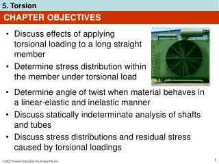
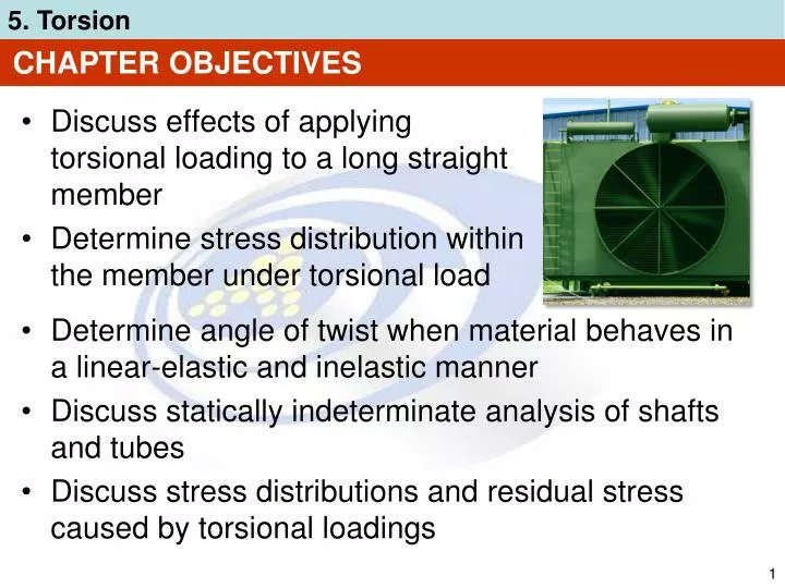
CHAPTER OBJECTIVES • Discuss effects of applying torsional loading to a long straight member • Determine stress distribution within the member under torsional load • Determine angle of twist when material behaves in a linear-elastic and inelastic manner • Discuss statically indeterminate analysis of shafts and tubes • Discuss stress distributions and residual stress caused by torsional loadings
CHAPTER OUTLINE • Torsional Deformation of a Circular Shaft • The Torsion Formula • Power Transmission • Angle of Twist • Statically Indeterminate Torque-Loaded Members • Stress Concentration
5.1 TORSIONAL DEFORMATION OF A CIRCULAR SHAFT • Torsion is a moment that twists/deforms a member about its longitudinal axis • By observation, if angle of rotation is small, length of shaft and its radius remain unchanged
Shaft Deformations • From observation, the angle of twist of the shaft is proportional to the applied torque and to the shaft length. • When subjected to torsion, every cross section of a circular shaft remains plane and undistorted. • Cross-sections for hollow and solid circular shafts remain plain and undistorted because a circular shaft is axisymmetric. • Cross-sections of noncircular (non-axisymmetric) shafts are distorted when subjected to torsion.
It follows that • Shear strain is proportional to twist and radius Shearing Strain • Consider an interior section of the shaft. As a torsional load is applied, an element on the interior cylinder deforms into a rhombus. • Since the ends of the element remain planar, the shear strain is equal to angle of twist.
Stresses in Elastic Range • Multiplying the previous equation by the shear modulus, From Hooke’s Law, , so The shearing stress varies linearly with the radial position in the section. • Recall that the sum of the moments from the internal stress distribution is equal to the torque on the shaft at the section,
Tc J max = 5.2 THE TORSION FORMULA • The integral in the equation can be represented as the polar moment of inertia J, of shaft’s x-sectional area computed about its longitudinal axis max = max. shear stress in shaft, at the outer surface T = resultant internal torque acting at x-section, from method of sections & equation of moment equilibrium applied about longitudinal axis J = polar moment of inertia at x-sectional area c = outer radius pf the shaft
5.2 THE TORSION FORMULA • The results are known as the elastic torsion formulas,
T J = 5.2 THE TORSION FORMULA • Shear stress at intermediate distance, • The above two equations are referred to as the torsion formula • Used only if shaft is circular, its material homogenous, and it behaves in an linear-elastic manner since the derivation is based on
2 J= c4 5.2 THE TORSION FORMULA Solid shaft • J can be determined using area element in the form of a differential ring or annulus having thickness d and circumference 2 . • For this ring, dA = 2 d • J is a geometric property of the circular area and is always positive. Common units used for its measurement are mm4 and m4.
2 J= (co4 ci4) 5.2 THE TORSION FORMULA Tubular shaft
Ductile materials generally fail in shear. Brittle materials are weaker in tension than shear. • When subjected to torsion, a ductile specimen breaks along a plane of maximum shear, i.e., a plane perpendicular to the shaft axis. • When subjected to torsion, a brittle specimen breaks along planes perpendicular to the direction in which tension is a maximum, i.e., along surfaces at 45o to the shaft axis. Torsional Failure Modes
5.2 THE TORSION FORMULA Absolute maximum torsional stress • Need to find location where ratio Tc/J is maximum • Draw a torque diagram (internal torque vs. x along shaft) • Sign Convention: T is positive, by right-hand rule, is directed outward from the shaft • Once internal torque throughout shaft is determined, maximum ratio of Tc/J can be identified
5.2 THE TORSION FORMULA Procedure for analysis Internal loading • Section shaft perpendicular to its axis at point where shear stress is to be determined • Use free-body diagram and equations of equilibrium to obtain internal torque at section Section property • Compute polar moment of inertia and x-sectional area • For solid section, J = c4/2 • For tube, J = (co4 ci4)/2
5.2 THE TORSION FORMULA Procedure for analysis Shear stress • Specify radial distance , measured from centre of x-section to point where shear stress is to be found • Apply torsion formula, = T /J or max = Tc/J • Shear stress acts on x-section in direction that is always perpendicular to
EXAMPLE 5.3 Shaft shown supported by two bearings and subjected to three torques. Determine shear stress developed at points A and B, located at section a-a of the shaft.
EXAMPLE 5.3 (SOLN) Internal torque Bearing reactions on shaft = 0, if shaft weight assumed to be negligible. Applied torques satisfy moment equilibrium about shaft’s axis. Internal torque at section a-a determined from free-body diagram of left segment.
EXAMPLE 5.3 (SOLN) Internal torque Mx = 0; 4250 kN·mm 3000 kN·mm T = 0 T = 1250 kN·mm Section property J = /2(75 mm)4 = 4.97 107 mm4 Shear stress Since point A is at = c = 75 mm B = Tc/J = ... = 1.89 MPa
EXAMPLE 5.3 (SOLN) Shear stress Likewise for point B, at = 15 mm B = T /J = ... = 0.377 MPa Directions of the stresses on elements A and B established from direction of resultant internal torque T.
Sample Problem 3.4 SOLUTION: • Apply a static equilibrium analysis on the two shafts to find a relationship between TCD and T0 . • Apply a kinematic analysis to relate the angular rotations of the gears. • Find the maximum allowable torque on each shaft – choose the smallest. Two solid steel shafts are connected by gears. Knowing that for each shaft G = 77 GPa and that the allowable shearing stress is 55 MPa, determine (a) the largest torque T0 that may be applied to the end of shaft AB, (b) the corresponding angle through which end A of shaft AB rotates. • Find the corresponding angle of twist for each shaft and the net angular rotation of end A.
Sample Problem 3.4 SOLUTION: • Apply a static equilibrium analysis on the two shafts to find a relationship between TCD and T0 . • Apply a kinematic analysis to relate the angular rotations of the gears.
Sample Problem 3.4 • Find the T0 for the maximum allowable torque on each shaft – choose the smallest. • Find the corresponding angle of twist for each shaft and the net angular rotation of end A.
5.3 POWER TRANSMISSION • Shafts are used to transmit power are subjected to torques that depends on the power generated by the machine and the angular speed of the shaft.
P = T (d/dt) P = T P = 2fT 5.3 POWER TRANSMISSION • Power is defined as work performed per unit of time • Instantaneous power is • Since shaft’s angular velocity = d/dt, we can also express power as • Frequency fof a shaft’s rotation is often reported. It measures the number of cycles per second and since 1 cycle = 2 radians, and = 2f, then power Equation 5-11
J c T allow = 5.3 POWER TRANSMISSION Shaft Design • If power transmitted by shaft and its frequency of rotation is known, torque is determined from Eqn 5-11 • Knowing T and allowable shear stress for material, allow and applying torsion formula,
5.3 POWER TRANSMISSION Shaft Design • For solid shaft, substitute J = (/2)c4 to determine c • For tubular shaft, substitute J = (/2)(co2 ci2) to determine co and ci
EXAMPLE 5.5 Solid steel shaft shown used to transmit 3750 W from attached motor M. Shaft rotates at = 175 rpm and the steel allow = 100 MPa. Determine required diameter of shaft to nearest mm.
1 min 60 s 2 rad 1 rev 175 rev min ( ) ( ) = = 18.33 rad/s T allow c4 2 c2 J c = = EXAMPLE 5.5 (SOLN) Torque on shaft determined from P = T, Thus, P = 3750 N·m/s Thus, P = T,T = 204.6 N·m . . . c = 10.92 mm Since 2c = 21.84 mm, select shaft with diameter of d = 22 mm
T(x) dx J(x) G L ∫0 = 5.4 ANGLE OF TWIST • Angle of twist is important when analyzing reactions on statically indeterminate shafts = angle of twist, in radians T(x) = internal torque at arbitrary position x, found from method of sections and equation of moment equilibrium applied about shaft’s axis J(x) = polar moment of inertia as a function of x G = shear modulus of elasticity for material
TL JG = TL JG = 5.4 ANGLE OF TWIST Constant torque and x-sectional area If shaft is subjected to several different torques, or x-sectional area or shear modulus changes suddenly from one region of the shaft to the next, then apply Eqn 5-15 to each segment before vectorially adding each segment’s angle of twist:
5.4 ANGLE OF TWIST Sign convention • Use right-hand rule: torque and angle of twist are positive when thumb is directed outward from the shaft
5.4 ANGLE OF TWIST Procedure for analysis Internal torque • Use method of sections and equation of moment equilibrium applied along shaft’s axis • If torque varies along shaft’s length, section made at arbitrary position x along shaft is represented as T(x) • If several constant external torques act on shaft between its ends, internal torque in each segment must be determined and shown as a torque diagram
5.4 ANGLE OF TWIST Procedure for analysis Angle of twist • When circular x-sectional area varies along shaft’s axis, polar moment of inertia expressed as a function of its position x along its axis, J(x) • If J or internal torque suddenly changes between ends of shaft, = ∫ (T(x)/J(x)G) dx or = TL/JG must be applied to each segment for which J, T and G are continuous or constant • Use consistent sign convention for internal torque and also the set of units
TA LAC JG TB LBC JG = 0 LBC L LAC L ( ) ( ) TA = T TB = T 5.5 STATICALLY INDETERMINATE TORQUE-LOADED MEMBERS • Assume linear-elastic behavior, and using load-displacement relationship, = TL/JG, thus compatibility equation can be written as • Solving the equations simultaneously, and realizing thatL = LAC + LBC, we get
5.5 STATICALLY INDETERMINATE TORQUE-LOADED MEMBERS • A torsionally loaded shaft is statically indeterminate if moment equation of equilibrium, applied about axis of shaft, is not enough to determine unknown torques acting on the shaft
5.5 STATICALLY INDETERMINATE TORQUE-LOADED MEMBERS • From free-body diagram, reactive torques at supports A and B are unknown, Thus, Mx = 0; T TA TB = 0 • Since problem is statically indeterminate, formulate the condition of compatibility; end supports are fixed, thus angle of twist of both ends should sum to zero A/B = 0
5.5 STATICALLY INDETERMINATE TORQUE-LOADED MEMBERS Procedure for analysis Equilibrium • Draw a free-body diagram • Write equations of equilibrium about axis of shaft Compatibility • Express compatibility conditions in terms of rotational displacement caused by reactive torques • Use torque-displacement relationship, such as = TL/JG • Solve equilibrium and compatibility equations for unknown torques
EXAMPLE 5.11 Solid steel shaft shown has a diameter of 20 mm. If it is subjected to two torques, determine reactions at fixed supports A and B.