Download
1 / 17
210 likes | 615 Views
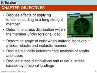
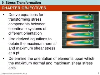
CHAPTER OBJECTIVES. Develop a method for finding the shear stress in a beam having a prismatic cross-section and made from homogeneous material that behaves in a linear-elastic manner This method of analysis is limited to special cases of cross-sectional geometry. CHAPTER OUTLINE.

E N D
CHAPTER OBJECTIVES • Develop a method for finding the shear stress in a beam having a prismatic cross-section and made from homogeneous material that behaves in a linear-elastic manner • This method of analysis is limited to special cases of cross-sectional geometry
CHAPTER OUTLINE • Shear in Straight Members • The Shear Formula • Shear Stresses in Beams
7.1 SHEAR IN STRAIGHT MEMBERS • Shear V is the result of a transverse shear-stress distribution that acts over the beam’s cross-section. • Due to complementary property of shear, associated longitudinal shear stresses also act along longitudinal planes of beam
Boards not bonded together Boards bonded together 7.1 SHEAR IN STRAIGHT MEMBERS • As shown below, if top and bottom surfaces of each board are smooth and not bonded together, then application of load P will cause the boards to slide relative to one another. • However, if boards are bonded together, longitudinal shear stresses will develop and distort cross-section in a complex manner
Before deformation Before deformation After deformation 7.1 SHEAR IN STRAIGHT MEMBERS • As shown, when shear V is applied, the non-uniform shear-strain distribution over cross-section will cause it to warp, i.e., not remain in plane.
VQ It = 7.2 THE SHEAR FORMULA • By first principles, flexure formula and V = dM/dx, we obtain Eq. 7-3 =shear stress in member at the point located a distance y’ from the neutral axis. Assumed to be constant and therefore averaged across the width t of member V = internal resultant shear force, determined from method of sections and equations of equilibrium
VQ It = 7.2 THE SHEAR FORMULA Eq. 7-3 I = moment of inertia of entire cross-sectional area computed about the neutral axis t = width of the member’s cross-sectional area, measured at the point where is to be determined Q =∫A’ydA’ = y’A’, where A’ is the top (or bottom) portion of member’s cross-sectional area, defined from section where t is measured, and y’ is distance of centroid of A’, measured from neutral axis
7.2 THE SHEAR FORMULA • The equation derived is called the shear formula • Since Eqn 7-3 is derived indirectly from the flexure formula, the material must behave in a linear-elastic manner and have a modulus of elasticity that is the same in tension and in compression • Shear stress in composite members can also be obtained using the shear formula • To do so, compute Q and I from the transformed section of the member as discussed in section 6.6. Thickness tin formula remains the actual width t of cross-section at the pt where is to be calculated
h2 4 1 2 ( ) Q = y’A’ = y2 b 7.3 SHEAR STRESSES IN BEAMS Rectangular cross-section • Consider beam to have rectangular cross-section of width b and height h as shown. • Distribution of shear stress throughout cross-section can be determined by computing shear stress at arbitrary height “y” from neutral axis, and plotting the function. Hence,
6V bh3 () = y2 h2 4 Shear stress distribution 7.3 SHEAR STRESSES IN BEAMS Rectangular cross-section • After deriving Q and applying the shear formula, we have Eq. 7-4 • Eqn 7-4 indicates that shear-stress distribution over cross-section is parabolic.
Eq. 7-4 V A max = 1.5 6V bh3 () Eq. 7-5 = y2 h2 4 7.3 SHEAR STRESSES IN BEAMS • At y = 0, we have • By comparison,max is 50% greater than the average shear stress determined from avg = V/A.
EXAMPLE-1 The beam shown in the figure is made of wood and is subjected to a resultant vertical shear force of V = 3 kN. Determine: The shear stress in the beam at point P. The maximumshear stress in the beam.
EXAMPLE-1 Part a) Section Properties: Moment of inertia about the neutral axis bh3 12 (100)(125)3 12 I == =16.28x106 mm4 A horizontal section line is drawn through point P and the partial area is shown shaded. Hence, the first moment with respect to the neutral axis is [12.5+(1/2)(50)][(50)(100)] mm3 =18.75x104 mm4
EXAMPLE-1 Shear stress at point P: VQ I t (3x10³)(18.75x10⁴) (16.28x10⁶)(100) tP== =0.346 N/mm2 =0.346 MPa
EXAMPLE-1 Part b) Maximum shear stress occurs at the neutral axis. Hence, the first moment with respect to the neutral axis is largest, thus =19.53x104 mm4 [62.5/2](100)(62.5) Shear stress maximum: VQ I t (3x10³)(19.53x10⁴) (16.28x10⁶)(100) tmax== =0.36 N/mm2 =0.36 MPa V A 3x10³ (100)(125) tmax= 1.5 = 1.5 =0.36 N/mm2 Note that this equivalent to
EXAMPLE-2 The steel rod has radius of 30 mm. If it is subjected to a shear force of V = 25 kN, determine the maximum shear stress. Section Property: Moment of inertia about the neutral axis 4 4 I =r4= (304) =0.636x106 mm4
EXAMPLE-2 Maximum shear stress occurs at the neutral axis. Hence, the height of the centroid is 4 3 4 3 r= (30) = 12.73 mm V The first moment with respect to the neutral axis is largest, thus Neutral axis _ y’ =18x103 mm4 [12.73][(302)/2] Shear stress maximum: VQ I t (25x103)(18x103) (0.636x10⁶)(60) tmax== =11.8 N/mm2 =11.8 MPa