Download
1 / 16
160 likes | 322 Views
Chapter Objectives. After completing this chapter you will be able to: Understand the ATM header information and how it is utilised Outline the UNI and NNI cell headers Describe the functions of the ATM layer. CS. Adaptation Layer. SAR. Layer two. ATM Layer. TC. Layer one.

E N D
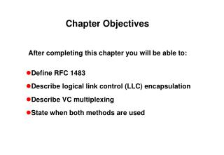
Chapter Objectives • After completing this chapter you will be able to: • Understand the ATM header information and how it is utilised • Outline the UNI and NNI cell headers • Describe the functions of the ATM layer
CS Adaptation Layer SAR Layer two ATM Layer TC Layer one Physical Layer PMD ATM Layer
Bits 1 8 GFC VPI 1st Octet VPI VCI 2nd Octet 3rd Octet VCI 4th Octet PTI VCI CLP HEC 5th Octet 48-octet data field UNI Cell Header
Bits 1 8 VPI 1st Octet VPI VCI 2nd Octet 3rd Octet VCI 4th Octet PTI VCI CLP HEC 5th Octet 48-octet data field NNI Cell Header
GFC VPI VPI VCI VCI CLP VCI PTI HEC 48-octet data field Generic Flow Control • Locally significant only (at UNI) • Any value will be overwritten by the switch • Two modes of operation: • Controlled mode • Uncontrolled mode • Currently only uncontrolled mode is defined • Uncontrolled GFC = 0000
VPI GFC VPI VCI VCI CLP VCI PTI HEC 48-octet data field Virtual Path Identifier • Identifies this cell’s path • 8 bits available at the UNI • 12 bits available at the NNI • 256/4096 possible simultaneous paths • Maximum number of usable bits is negotiable between user and network ‘Real’ physical link VPI 57 VPI 68
VCI 39 VPI 68 VCI 39 VPI 57 VPI GFC VCI 40 VCI44 VPI VCI VCI 38 VCI 40 VPI 68 VPI 68 VCI VCI 41 VCI 39 CLP VCI PTI HEC 4- octet data field Physical Interfaces Virtual Channel Identifier • Identifies this cell’s channel • 16 bits available at the UNI & NNI • 65,536 possible simultaneous channels per path • Maximum number of useable bits is negotiable on a per-path basis
channels 131 145 117 Multiple channels destined for a common location can be quickly and simply switched by the network if they share a common VPI channels 131 145 117 Virtual Paths
Reserved Virtual Connections • The following VPI/VCI combinations have been reserved: • VPI = 0 VCI = 0 to 15 ITU-T • VPI = 0 VCI = 16 to 31 ATM Forum • VPI = ALL VCI = 1 to 5 • In practice, carriers regard VCIs 0 to 31 as reserved for all VPIs
GFC VPI VPI VCI PTI Coding VCI Interpretation (MSB first) CLP VCI PTI HEC User data cell, congestion not experienced, SDU type = 0 000 48-octet data field User data cell, congestion not experienced, SDU type = 1 001 User data cell, congestion experienced, SDU type = 0 010 User data cell, congestion experienced, SDU type = 1 011 Segment OAM F5 flow-related cell 100 End-to-end OAM F5 flow-related cell 101 Resource management cell 110 Reserved for future functions 111 Payload Type Identifier
EFCI GFC VPI VPI VCI VCI CLP VCI PTI HEC 48-byte data field Congestion Control • Bit 2 of the PTI may be used to indicate to the destination that congestion has taken place in the network • The bit is called Explicit Forward Congestion Indicator (EFCI) • This will occur when switches are discarding cells with CLP =1
CLP = 1 CLP = 0 CLP = 1 CLP = 0 GFC VPI VPI VCI VCI Private UNI Private NNI Public UNI Public NNI CLP VCI PTI HEC 48-octet data field Cell Loss Priority • CLP operates independently on each active VPI/VCI • A switch may flip CLP from 0 to 1, for example, if traffic on a VPI/VCI exceeds the maximum agreed sustainable cell rate
GFC VPI VPI VCI VCI CLP VCI PTI HEC 48-octet data field Header Error Check • The HEC is performed on the header only • Supports forward correction of single-bit errors • Supports detection of multiple-bit errors • Faulty cells are discarded • At the UNI: • Error detection is mandatory • Error correction is optional • The HEC is generated/verified at the TC part of the physical layer
ATM Switch Virtual Channel Switch VCI1 VCI2 VCI3 VCI4 VPI1 VPI2 VPI5 VCI4 VPI5 VCI3 VCI1 VPI1 VPI2 VCI2 VCIa VCIa VPI3 VPI4 VCIb VCIb Virtual Path Switch Virtual Paths and Channels
CPE B CPE A Switching Node Virtual Channel Link Virtual Channel Link Virtual Channel Connection Virtual Paths and Channels
ATM Cell ATM Cells 1 2 VPI/VCI = A/B VPI/VCI = X/Y Switch Map (1) VPI VCI Interface VPI VCI A B 2 X Y - - - - - VPI/VCI is of LOCAL Significance Only The Switch Map