Download
1 / 23
240 likes | 388 Views
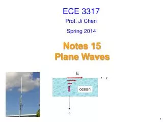
ECE 3317. Prof. Ji Chen. Spring 2014. Notes 10 Transmission Lines ( Reflection and Impedance). Reflection. Z g. I( z ). +. Z 0. V( z ). Z L. S. -. z = 0. z. Consider a transmission line that is terminated with a load:. S inusoidal source.

E N D
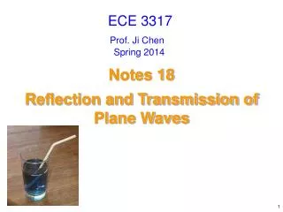
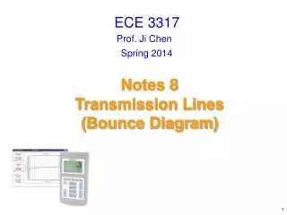
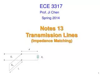
ECE 3317 Prof. Ji Chen Spring 2014 Notes 10 Transmission Lines(Reflection and Impedance)
Reflection Zg I(z) + Z0 V(z) ZL S - z = 0 z Consider a transmission line that is terminated with a load: Sinusoidal source Voltage and current on the line:
Reflection (cont.) Zg I(z) + Z0 V(z) ZL S - z = 0 Important point: The forward-traveling and backward-traveling wave amplitudes are the amplitudes that describe the two waves in sinusoidal steady-state (after all bounces have died down and we are in steady state). A = amplitude of net forward-traveling wave B = amplitude of net backward-traveling wave
Reflection (cont.) Zg I(z) + Z0 V(z) ZL S - z = 0 z At the load (z = 0): Hence we have or
Reflection Coefficient We define the load reflection coefficient: Hence We then have or
Voltage and Current We can then write Note: The generator (source) will determine the unknown (complex) constant A.
Impedance Zg I(z) S + Z0 V(z) ZL - z = 0 Zin z We define the input impedance at any point on the line
Impedance (cont.) We then have Canceling the constant A, we have or
Impedance (cont.) Substituting for the load reflection coefficient, we have
Impedance (cont.) Rearranging the expression, we have Now let z = - l
Impedance (cont.) S Zg I(z) + Z0 V(z) ZL - l Zin We then have
Impedance (cont.) Limiting cases 1) General (lossy) line: 2) Lossless line: These limiting cases agree with circuit theory.
Impedance (cont.) Limiting cases (cont.) 3) Lossy infinite line:
Impedance (cont.) Lossless Case Use We then have where
Impedance (cont.) Zin Z0 ZL l Summary of final formula for a lossless line
Impedance (cont.) For a lossless line: The input impedance repeats every one-half wavelength. The voltage and current repeat every wavelength. The magnitude of the voltage and current repeat every one-half wavelength. The voltage and current become their negatives after one-half wavelength.
Impedance (cont.) Zin Z0 ZL = 0 l Special Cases of Lossless Line Short-circuit line or
Impedance (cont.) Short-circuit line or The line is one-half of a wavelength long. Xin inductive l π/2 3π/2 5π/2 capacitive
Impedance (cont.) Low frequency: Short-circuit line Ll Cl Zin l
Impedance (cont.) Zin Z0 ZL = l Special cases of Lossless Line (cont.) Open-circuit line or
Impedance (cont.) Open-circuit line or Xin The line is one-half of a wavelength long. inductive l π 2π 3π capacitive
Impedance (cont.) Low frequency: Open-circuit line Ll Cl Zin l
Filter Application Microstrip filter (application of open-circuited “stubs”)