Download
1 / 26
260 likes | 504 Views
Design of local shielding for the IFMIF/EVEDA beam dump. M. García 1,2 , F.Ogando 1,2 , P. Ortego 3 , J.M. Arroyo 4 , B.Brañas 4 , C. Töre 3 , D. López 1,2 , P. Sauvan 1,2 , A. Mayoral 1 , J. Sanz 1,2 1) UNED, C/ Juan del Rosal 12, 28040 Madrid, Spain

E N D
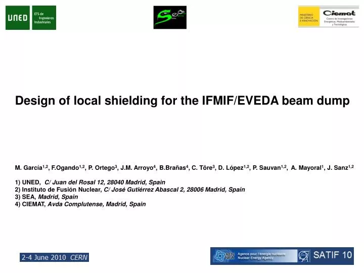
Design of local shielding for the IFMIF/EVEDA beam dump M. García1,2, F.Ogando1,2, P. Ortego3, J.M. Arroyo4, B.Brañas4, C. Töre3, D. López1,2, P. Sauvan1,2, A. Mayoral1, J. Sanz1,2 1) UNED, C/ Juan del Rosal 12, 28040 Madrid, Spain 2) Instituto de Fusión Nuclear, C/ José Gutiérrez Abascal 2, 28006 Madrid, Spain 3) SEA, Madrid, Spain 4) CIEMAT, Avda Complutense, Madrid, Spain
Introduction and Scope of the problem • Methodology • Design and optimization of the IFMIF/EVEDA Beam Dump shielding • Results • Conclusions
Introduction and Scope of the problem • Methodology • Design and optimization of the IFMIF/EVEDA Beam Dump shielding • Results • Conclusions
INTRODUCTION AND SCOPE OF THE PROBLEM: FRAMEWORK Work within the frame of the: Spanish participation in IFMIF/EVEDA Accelerator System Group • Design and construction of a Beam Dump for the EVEDA accelerator prototype • Radioprotection and Safety • two European home-teams involved for the EVEDA phase: • CEA (France) and UNED/CIEMAT (Spain).
INTRODUCTION AND SCOPE OF THE PROBLEM: FRAMEWORK Work within the frame of the: Spanish participation in IFMIF/EVEDA Accelerator System Group • Design and construction of a Beam Dump for the EVEDA accelerator prototype • Radioprotection and Safety • two European home-teams involved for the EVEDA phase: • CEA (France) and UNED/CIEMAT (Spain).
INTRODUCTION AND SCOPE OF THE PROBLEM: IFMIF/EVEDA Each deuteron accelerator: 125 mA up to 40 MeV 1017 neutrons/s 14 MeV
INTRODUCTION AND SCOPE OF THE PROBLEM: IFMIF/EVEDA EVEDA Phase: Engineering Validation and Design. IFMIF/EVEDA • Deuterons up to 9 MeV • 125 mA • Beam Dump In construction phase at Rokkasho (Japan)
INTRODUCTION AND SCOPE OF THE PROBLEM: IFMIF/EVEDA North: Limit 12.5 Sv/h Concrete thickness fixed 1.5m East: Limit 0.5 Sv/h West: 0.5 Sv/h South: Limit 12.5 Sv/h Copper cone: to stop deuteron beam For the present design of both building and copper Beam Stop, we explore if a local BD shielding could be defined in compliance with two radioprotection requirements: 1.- Are the dose rates outside the accelerator vault during accelerator operation below the required levels for workers and public? (workers 12.5 Sv/h, public 0.5 Sv/h) 2.- Is man-access for maintenanceinside the accelerator vault feasible during beam- off phases?
INTRODUCTION AND SCOPE OF THE PROBLEM: IFMIF/EVEDA Beam Dump geometry: • Inner cone of 5mm thickness, 300mm base diameter and 2500 mm length. • Water channel (refrigeration) of 7mm thickness • Outer cone of 3mm thickness • Water (refrigeration) between the outer cone and the cartridge • Cylindrical cartridge made of steel of 9mm thickness. Outer diameter of the cartridge: 508mm Neutron source to shield: 4.6484 1014 n/s
INTRODUCTION AND SCOPE OF THE PROBLEM: IFMIF/EVEDA Deuteron deposition in the copper cone
Introduction and Scope of the problem • Methodology • Design and optimization of the IFMIF/EVEDA Beam Dump shielding • Results • Conclusions
METHODOLOGY: GENERAL OUTLINE TraceWin Module for Deuteron source modeling Module for neutron Source modeling Neutron and gamma Fluxes Neutron and deuteron fluxes ACAB Isotopic inventory & Gamma Source BEAM OFF BEAM ON MCNPX Dose conversion factors (ICRP74) Dose conversion factors (ICRP74) Neutron and gamma Doses Gamma Dose
METHODOLOGY: GENERAL OUTLINE • Obtaining the neutron source increases significantly the efficiency of the Monte Carlo • simulation since in deuteron-Cu interaction around 10000 deuterons are needed to • produce one neutron • How to model the neutron source due to the deuteron interaction with the copper cone? • The starting point is the deuteron particle position and energy at the copper cone • entrance provided by the TraceWin code. • First step: to determine the equivalent deuteron source point taking into account the • energy and particle deposition of the deuteron beam in the copper cone from TraceWin • Second step: to obtain the neutron source arising from the deuteron-copper interaction
Introduction and Scope of the problem • Methodology • Design and optimization of the IFMIF/EVEDA Beam Dump shielding • Results • Conclusions
DESIGN AND OPTIMIZATION OF THE IFMIF/EVEDA BEAM DUMP SHIELDING • Water-based preliminary design: • Starting point • 1 meter water shielding lateral and rear
DESIGN AND OPTIMIZATION OF THE IFMIF/EVEDA BEAM DUMP SHIELDING • Water-based preliminary design: • Starting point • 1 meter water shielding lateral and rear • Lateral gamma doses by (n,g) reactions cause doses higher than the limit • Dose by neutrons in the north produces dose rates higher than the limit • An optimization of the shielding is needed AMBIENT DOSE EQUIVALENT RATE BY NEUTRONS (Sv/h) AMBIENT DOSE EQUIVALENT RATE BY PHOTONS (Sv/h)
DESIGN AND OPTIMIZATION OF THE IFMIF/EVEDA BEAM DUMP SHIELDING • Optimized design (lateral area): • Considering better lateral shield which works on both neutron and gamma rays, • there is a need for at least two layers of different materials: • Internal shield to absorb and/or moderating the energetic neutron flux from beam stop. • External shield to attenuate the gamma rays originated in the internal shield from (n,g). • Front-lateral shield (removable) Optimized configuration: 50 cm water + 25 cm iron 30 cm polyethylene + 25 cm iron
DESIGN AND OPTIMIZATION OF THE IFMIF/EVEDA BEAM DUMP SHIELDING • Optimized design (front area): • Diagnostics room: Designed to: • Confine the highest residual dose rates allowing manual maintenance in the accelerator area • Reducing prompt dose rates in the north wall by collimating the neutron current escaping the beam dump during operation • Lead shutter: Designed to reduce residual dose rates in the accelerator area BD cell Accelerator area Diagnostics room Lead shutter
DESIGN AND OPTIMIZATION OF THE IFMIF/EVEDA BEAM DUMP SHIELDING North Diagnostics room Beam Dump cell Area East West dipole iron water South quadrupoles This is a conceptual design polyethylene Accelerator Area • Beam Dump cell area: • Lateral and rear shielding: water (50 cm) + iron (25 cm). Fixed solution. • Front-lateral shielding: polyethylene (30 cm) + iron (25 cm). Removable solution. • Accelerator area: • Diagnostics room: to confine higher beam-off dose rates and allow manual • maintenance in the accelerator area on beam-off phase.
Introduction and Scope of the problem • Methodology • Design and optimization of the IFMIF/EVEDA Beam Dump shielding • Results • Conclusions
RESULTS: MAXIMUM PROMPT DOSE RATES AT THE EXTERNAL SURFACES Maximum prompt dose rates (external surfaces) Diagnostics room Ambient dose equivalent rate Beam Dump cell Area dipole iron water quadrupoles polyethylene Accelerator Area Effect of diagnostics room on dose rate by neutrons Without room With room Ambient dose equivalent rate
RESULTS: RESIDUAL DOSE RATES INSIDE THE ACCELERATOR VAULT Residual dose rates (irradiation 6 months continuous full power, 1 day cooling time) Lead plug thickness: 9 cm Lead sheet thickness: 1 cm Beam-off configuration: Ambient dose equivalent rate Manual maintenance is possible in the Beam Dump cell and In the accelerator area without restrictions (dose rates lower than 12.5 µSv/h).
Introduction and Scope of the problem • Methodology • Design and optimization of the IFMIF/EVEDA Beam Dump shielding • Results • Conclusions
CONCLUSIONS • A beam dump shield for the IFMIF/EVEDA facility has been designed. • This model makes use of an optimized combination of materials for neutron and • photon shielding and has been achieved after successive optimization steps. • The main goals achieved of the design are: • 1. Maximum beam-on dose rates outside the accelerator vault fulfill the limits • (both in the close workers areas and outside the facility for public). • 2. Maximum beam-off dose rates allow hands-on maintenance in most of the • accelerator vault, reducing the high dose rate area to a small dedicated room. • Future work must be focused on i) diagnostics room optimization and ii) specific • solutions for the construction phase.