Download
1 / 55
580 likes | 1.08k Views
SESAME. SESAME = S ynchrotron-light for E xperimental S cience and A pplications in the M iddle E ast . Outline. History Management Injector Storage-Ring-Magnets Storage-Ring-RF Storage-Ring-Vacuum Shielding Cooling Beam-Lines. The Evolution of SESAME.

E N D
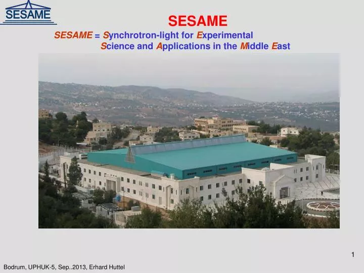
SESAME SESAME= Synchrotron-light for Experimental Science and Applications in the Middle East
Outline History Management Injector Storage-Ring-Magnets Storage-Ring-RF Storage-Ring-Vacuum Shielding Cooling Beam-Lines
The Evolution of SESAME 1990’s: A scientific cooperation as a vehicle of peace in the Middle East been proposed;I n particular, Middle East Scientific Cooperation (MESC) group, based at CERN(Sergio Fubini, Eliezer Rabinovici, Herwig Schopper, Tord Ekelof…) 1997: Original idea (Voss, Winick); Upgrade/rebuild BESSY 1(0.8 GeV) in the Middle East, as centerpice for a new international research center. Voss presents the concept to a MESC meeting in Turino. 1999: 1st meeting at UNESCO; (Interim) Council established – Herwig Schopper, President. 2002 - Decision to build a new 2.5 GeV ring (still using BESSY injector) 2003 - Ground breaking for building; completion in 2008 2008 – Chris Llewellyn-Smith takes over as Council President
SESAME-Mission Foster excellent science and technology in the Middle East (and prevent or reverse the brain drain Build bridges between diverse societies SESAME-Members: Bahrain, Cyprus, Egypt, Israel, Iran, Jordan, Pakistan, Palestin, Turkey. Observers: Brazil, China, France, Germany, Greece, Italy, Japan, Kuwait, Portugal, Russia, Sweden, Switzerland, UK and USA.
The means have become available to built up SESAME now! CERN/EU contribute 5 M€ for the purchasing of the magnet system. Iran, Israel, Jordan, Turkey will contribute 5 M$ within next four years. Italy will contribute 1 M €. Pakistan might contribute in kind.
Financial Aspects till 2016 Injector-upgrade 0.9 M€ Magnets and PS:5.0 M€ Girder: 0.8 M€ Vacuum: 3.0 M€ RF: 3.0 M€ Diagnostics: 1.5 M€ SR-Cooling: 0.5 M€ Cabling: 0.5 M€ Commissioning: 1.5 M€ Control-System 1.1 M€ Safety P+A 0.8 M€ Front-Ends: 0.5 M€ Sum [€] 19.0 M€ Sum [$] 23.3 M$ 10% 25.6 M$ Income EU-CERN: 5.00 M€ Jordan: 4 x 1.25 M$ Turkey: 4 x 1.25 M$ Israel: 4 x 1.25 M$ Iran: 4 x 1.25 M$ ? Sum: 26 M $ ? Machine: 25.6 M$ 4 Beamlines upgrade: 8.7 M$ Guesthouse+ 1.3 M$ Sum 35.6 M$
Operational-Cost-Development Power: Based on 4000 h operation time, 10 GWh / y Salary: Increase 35-75 employees
Organization Beamlines XABS:Messaoud Harfouche IR: Ibraheem Yousef Open Position 2012 Electronics/Electric Sofian Javar (Power supplies) Ifikhar Abid (pulsed PS) Osama Khader (Electric) Yazeed Momani (beam-lines) Farouq Al-Omari (beam-lines) Cooling/Vacuum Firas Mahahleh Osama Nour Mohammad Al-Nadjdawi Adel Amro Saed Budair Machine-Physics Maher Attal (optics,+). Mohammad Ebeni (Jan.2013, magnets) Koryun Maunkyan (2013). Computing Salman MAtalgah Mustafa Zoubi Control (Ziaulhaque Qazi) left 2013 Ibrahim Saleh Abdallah Ismail Design/Mechanics Maher Shehab Thaer Abu-Hanieh Akrum Al-Homoud Ahmad Ateieh Open position 2012 N.N. RF/Diagnostics Darweesh Foudeh Nashat (RF) Alaa Alkurdi (RF) Hussain Al-Mohammad (D) Radiation-Safety Adli Hamad Morteza Mansouri Administration Sonia Al-Faques (Assistant) Majeda Salama ( Purchasing) Ayman Al-Zoubi (Human resources) Ibrahim Radwan (Accountant) Abd Al Mawla Gnaimat(Bus-driver) Khaled Al-Zoubi (2013 Bus-driver)
Layout of SESAME Experimental Hall IR 3 Accelerator Microtron: 20 MeV Booster: 800 MeV Storage-ring: 2500 MeV EUV BL SAXS-WAXS PX VUV PD XRF-XAFS
SESAME Microtron in Operation, Beam in the transfer line Magnet Field: 0.112 T Diameter: 2.22 m Energy gain/turn: 0.535 MeV Max. e-Radius: 0.67 m No turns: 42 RF frequency: 3.00 GHz RF-Peak-Power: 2 MW Achieved: Energy: 22MeV Pulse-Width: 1 µs Pulse-Current: 4 mA 3 mm 4.4 mm
Pulsed Magnets Parameter General Policy for the Booster: Keep BESSY Magnets. Replace Power-Supplies.
Booster-Optics vert. foc. qp. horiz.foc.qp dipole
Power-Supplies and Control To warranty reliability: All Power-supplies and Control-units will be new. PLC Booster-control-rack Main Magnet PS; 4-quadrant DP: 1000 A, +/- 350 V QF: 120 A , +/- 100 V QD: 120 A , +/- 50 V Vacuum chamber mounting 05.06.2013
Storagering Half Cell SESAME: 16 x 140 T/m2 10 T/m 17 T/m 1.46 T -2.79 T/m 90 T/m2
SESAME-Optics Low vertical beta Beta function: βx, βy: σx = √(εx βx) σx‘ = √(εx /βx )
Dynamic Aperture Electron beam size about 1x0.1 mm2 Some Electrons are scattered into cm range. Might not get focused again and get lost. Dynamic Aperture gives space, they are captured again. Tune (hx, hy) : Scattered electrons oscillate with hx, hy cycles per revolution. If hx, hy has certain values, oscillations are not damped. Particles can get lost.
CESSAMag-Project CERN SESAME agreement: 15.05.2012 EU CERN agreement FP7: 11.04.2013 CERN Jean-Pierre Koutchouk DavideTommasini Attilio Milanese Louis Walckiers Theodor Tortschanoff SESAME Erhard Huttel Maher Attal Maher Shehab FirasMakahleh Mohammad Ebeni ALBA Montse Pont Design done! Design-Reports done (Attilio Milanese (CERN))! Multipole tolerances for magnets defined (Maher Attal) Specification written, approved, (published) Request for Tender out, closed Contracted to (still confidential)
Storagering Magnets Dipole: B: 1.46 T B’:2.79 T/m L: 2.25 m Quadrupole: B’: 17 (-9) T/m L: 0.28 (0.1) m Sextupole: M: 90 (-140) T/m2 l.: 0.1 m First punched laminations
Magnet Specification • Steel: • Lamination: 1 mm • Burr: < 25 µm • Coercitifity: < 70 A/m • Carbon content: < 50 ppm • Silicon: < 100 ppm • H [A/m] – B [T] • 1.52 • 2500 1.63 • 1.71 • 10000 1.81 Mechanical tolerances DipoleLamination: Form-tolerance (pole): < 30 µm Form-tolerance (interface): < 50 µm Flatness: < 50 µm Yoke: Length: < 0.5 mm Angularity: < 0.1 mm Flatness (pole): < 0.1 mm Tolerances ~ 50 µm Mechanical Tolerances Quadrupole Lamination: Form-tolerance (pole/else):< 30/100 µm Angularity: : < 30 µm Shim-distance, p-p: < 30 µm Diameter distance p-p: < 50 µm Planarity: < 50 µm Yoke: Length: < 0.5 mm Angularity: < 0.05 mm Planarity: < 0.05 mm Shuffling Swopping Coils: 2 thermo coupler per coilIsolation test: 5 kV Inductance, p-p: < 4 % Resistivity, p-p: < 2 %
Girder-Design Design ready 6 feeds 3 struts used for transverse and longitudinal adjustment 3 jacks used for vertical adjustment and clamping Magnet Position defined by pins
Girder-Design Vacuum chamber lifted in from top Dipole to be moved out by trolley
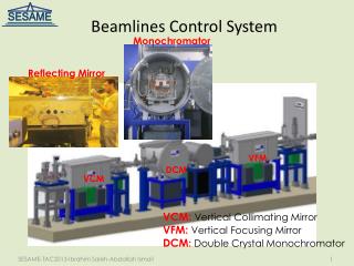
RF for Electron-Synchrotrons Low energy electrons High energy electrons Electrons with higher energy take longer path , see less voltage U = 26.5 E3 B
Cavities Radiated Synchrotron Radiation Power has to be compensated by the RF system 500 MHz Microwave feed into cavities. Type of cavities not yet decided: KEK II/PF, Elettra, EU
500 MHz 80 kW Solid-State-Amplifier X 16 X 10 4 x 0.65 kW 10 kW 80 kW Syn.Rad. Losses: (200 mA 600 kV) / 4 = 30 kW Cavity Losses: (400 kV)2 / (6 MΩ)= 25 kW 4 Cavities: 220 kW
Vacuum-Chamber Pressure < 2 10-9 mbar for lifetime > 10 h Syn.Rad. is absorbed on lumped absorber, Pumps beneath Syn.Rad. is passing into ante chamber Electron beam chamber 70 x 28 mm2 Installed Ion-Pumps: 16 x ( 2x 300 l/s + 7 150 l/s)
Vacuum-Pumps SIP2 300 l/s SIP3 300 l/s SIP1 150 l/s TSP 2 SIP4 (150 l/s) TSP 1 SIP5 150 l/s SIP7 150 l/s SIP6 150 l/s SIP5 150 l/s SIP6 150 l/s
Vacuum Development SR hits wall Gases are desorpt SR cleans wall, vacuum is improving lifetime is increasing Nph = 8 1020 I(A) E (GeV) = 4 1020 p(mbar) = 4 10-20ηNph/ S Seff = 15 000 l/s η = 10-3 - 10-6 p(mbar) = 10 -6 - 10-9 η = 10-3 η = 10-6
ANKA,SLS,..SOLEIL (Heidenreich PSI) Tmax: 150 Tbound: 50 Tmax: 123 Tbound: 30 Stress reduction by allowing expansion
Lifetime Elastic scattering τelastic: ~ 1/p E2 (a / β)2 Inelastic scattering τinelastic: ~ 1/p ln(dε/ ε) Touscheck τtouscheck: ~ E2σx σyσz (d ε / ε)3 / IB Pressure p (N2): 10-9 mbar Energy acceptance dε / ε : 1.5 % Bunch size σx: 0.5 mm σy: 0.1 mm σz: 10 mm Bunch current IB: 2.5 mA
Shielding / Radiation Safety Allowed dose: < 1 mSv/y (Allowed dose for Non-Radiation Workers) Electron -loss: γ,n cascade 2500 MeV Inelastic scattering: gas-Bremsstrahlung 25 MeV Synchrotron Radition: 50 keV Side-Wall: 1m concrete Front-Wall:1m concrete +0.15 m lead Radiation Monitor
Radiation-Safety Rules: Keep radiation level < 1 mSv / y (2000 h) 0.5 µSv/h Radiation Monitors purchased: 5 movable +2 portable stations: Gamma: 10 nSv/h – 1 Sv/h 30 keV -10 MeV Neutrons: 10 nSv/h – 0.1 Sv/h 25 meV – 100 MeV Offline-Monitoring (TLT) local provider with coarse monitoring Bids closed for interlock system based on Safety PLC
Cooling System Chillers, Cooling towers Tunnel Air conditioning Heat-exchanger, Pumps
Power Design by SESAME (FirasMakahleh) Done by local provider: (Alpha-Amman) Volume: 2 M $, Built up: 2011-2013 Electric Power Cooling Capacity Cooling Tower Compressor 400 kW 2x 1 115 kW Chilling water tank Pumps 100 kW Heat Exchanger 2 x 870 kW Pumps 120 kW Air-Conditioning 300 kW 600 kW De Ionized Water Circuits: SR Magnet 500 kW RF Amplifier 250 kW RF-Cavities 200 mA 125 kW SR Absorber (200 mA) 125 kW Booster (PS) 100 kW Sum 2 000 kW
Control System Architecture Control-room: Linux-PC GUI: EDM (↓) → CSS Ethernet replaced by Server Layer: Virtual Servers (EPICS Middle layer) Ethernet Moxa Field Layer: PLC Embedded Controller VME (↓) no longer continued
Field-Devices BO-Vacuum-PLC IonPump controller Splitter box IMG controller Master-oscillator Moxa VME crate MRS Timing
Day One Beamlines To be done: Employ Beamline-Scientist for PD and PX Do Lab set up of PD beamline Do Lab set up of PX beamline e-critc.: 6 keV e-critc.: 19 keV e-critic: 0.665 E2 B
What is Synchrotron Radiation? Accelerated electrons emit ‚Electromagnetic Waves‘ Electrons in a dipole ‘move‘ like the ones in an antenna. The ‚antenna‘ is moved (by speed of light). The waves are compressed in forward direction. The radiation becomes ‚harder‘ : microwave, light, x-rays. The radiation is peaked in forward direction.
Insertion Device Dipole: one large radiation fan Insertion: n superimposed small radiation fans
XAFS-Beamline (ROBL-ESRF) Beamline Components set up in lab Under Test with ESRF experts