Download
1 / 15
150 likes | 416 Views
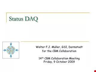
NPD09. CMD-3 DAQ hardware : features and status. A.Ruban*, A.Aulchenco, A.Kozyrev, A.Selivanov, L.Smolina, V.Titov BINP, Novosibirsk. Moscow, ITEP, November, 23-27,2009. CMD-3 DAQ hardware: features and status. Moscow, ITEP, November, 23-27,2009. 1 – Vacuum Pipe 2 – Drift Chamber

E N D
NPD09 CMD-3 DAQ hardware : features and status. A.Ruban*, A.Aulchenco, A.Kozyrev, A.Selivanov, L.Smolina, V.Titov BINP, Novosibirsk. Moscow, ITEP, November, 23-27,2009
CMD-3 DAQ hardware: features and status. Moscow, ITEP, November, 23-27,2009 1 – Vacuum Pipe 2 – Drift Chamber 3 – BGO Endcap Calorimeter 4 – Z–Chamber 5 – Superconducting Solenoid CMD-3 6 – LXe Calorimeter 7 – CsI Calorimeter 8 – Yoke 9 – Superconducting magnet lenses Mu-System and TOF are not showed CMD – 3 Subsystem Layout
CMD-3 DAQ hardware: features and status. Moscow, ITEP, November, 23-27,2009 • General requirements for DAQ • Total number of channel is about 10k • Average speed of good events – 1k Evtps • Low Cost, low EMI, low Power • Step-by-step inferring capability, support for legacy system • Specific requirements for DAQ • Precise time resolution – less then 20ps • Low, well-known level of error rate • Precise leave and dead time control • Precise analog channel efficiency control • Precise Trigger efficiency control • CMD-3 and VEPP2000 specific environment • Low energy deposition per cell – low primary signals • Relatively small size of cell – preamplifiers and shielding is space constrained • Tight, high density layout, cross interference aware • High pick-up from power supply of accelerator facility
CMD-3 DAQ hardware: features and status. Moscow, ITEP, November, 23-27,2009 When CMD-3 DAQ project starts the CERN S-Link and Belle Copper system exists. But it was very “heavy” to start, power angry and expensive. To satisfy the CMD-3 requirements the new Time Oriented Measurement and Acquire (TOMA) DAQ is designed. Typically modern HEP DAQ hardware has very complicated hierarchical design. The main feature of TOMA DAQ is exchange of hardware hierarchical complexity to synchronization modes hierarchical complexity. It means different modes of synchronization are organized in hierarchy levels and each specific mode is assigned to specific task. Thus it is possible to make hardware in single range level, or Flat Model Approach. In conjunction with modern FPGA’s “natural parallelism” it allows to use modular design of hardware with a little cross-dependence of modules. Obviously, it is the way to built reusable IP which will be common for all kind of boards in DAQ. To support system unification and man-power saving two “building block” was designed. It are “Skeletal Design” and “C-Link”.
CMD-3 DAQ hardware: features and status. Moscow, ITEP, November, 23-27,2009 This picture demonstrates so-called Skeletal Design which is created for and used in all boards of TOMA DAQ. It is parameterized HDL-description suitable for low-cost FPGA. The design is built as a Flat Model approach. Adding or removing of board specific modules does not affect functionality of another modules in the design. TOMA DAQ Skeletal Design
CMD-3 DAQ hardware: features and status. Moscow, ITEP, November, 23-27,2009 All synchronization and data transferring in TOMA DAQ is provided by single specially developed tool. While well-known S-link is designed to hide all synchronization detail, our tool is intended to obtain all chronopher functions, thus it is called C-Link. Note, please, this is NOT a mezzanine at physical layer, this is part of FPGA design. C-Link modules and it’s interface is designed in flat model approach.
CMD-3 DAQ hardware: features and status. Moscow, ITEP, November, 23-27,2009 Simple Synchronous mode is used to generate Time Stamps (Common Stop) in Time measuring Boards. Start bit of each transaction is sampled at reference Phase. Generally this sampling circuit is implemented as specific fast channel, bypassing FPGA and any complex logic IC. While LVDS level is recommended, it is compatible to use a LVPECL electric layer. It is possible to reach good enough jitter performance. The drawback of this “simple” method is tight requirements for relative phase shifts of all signals for all boards involved. It is real problem for HEP’s DAQ.
Mesochronous mode of synchronization is used within triggering boards to carefully align data sampling and frame generating time. This method allows to fine compensate differences in detector’s subsystem latency. Calibrating Generator boards will utilize this mode too. Mesochronouse mode does not interfere with synchronous mode because It is not necessary to exact control for PLL phase shift. Trigger time resolution is close to Local Clock period and a programmable Offset value brings enough grade of control. CMD-3 DAQ hardware: features and status. Moscow, ITEP, November, 23-27,2009
CMD-3 DAQ hardware: features and status. Moscow, ITEP, November, 23-27,2009 • Well-known Plesiochronous mode of synchronization is used for Command and Data movement during transaction. This method is not sensitive to any phase shifts thus it does not interfere with other synchronization modes used in DAQ. Any local clock which is satisfying Nyquist oversampling criteria can be used to synchronize the processing of a data. C-Link data/command stack
CMD-3 DAQ hardware: features and status. Moscow, ITEP, November, 23-27,2009 Asynchronous mode is used to collaborate with universal tools, such as an oscilloscope, pulse generator, etc. This mode signals is NIM levels. Dedicated time-to-digital converters channel allows to check asynchronous signals arrival time. It is the way to preserve good time resolution during resynchronization process. Isochronous mode of synchronization is used to change status of DAQ. The broadcast-like commands are distributed at each case DAQ need to change the status. Each board in DAQ accepts this command and execute associated Command List. It rewrites configuration registers of a Board causing a status to change. Exact moment of change depends of instruction number. It is guaranteed all Boards will change status within current transaction (i.e. within current event). This is looks like ordinary event with standard parameters, thus it can be written to tape and is suitable for off-line run processing. Isochronous mode is also used to collaborate with legacy DAQ. It allows cross-check of event number, dead time and other parameters. The Command List technology allow Boards with different internal structure to be adopted for the same kind action in DAQ.
Table of synchronization modes used in CMD-3 TOMA DAQ. CMD-3 DAQ hardware: features and status. Moscow, ITEP, November, 23-27,2009
CMD-3 DAQ hardware: features and status. • Trigger Data Pipeline Synchronization • Event Queue and Time Control • Data Collection • Status Control and Check • Calibration CMD-3 TOMA DAQ layout
CMD-3 DAQ hardware: features and status. Moscow, ITEP, November, 23-27,2009 • End-to-end testability • On-line data transfer check • On-line signal condition and error rate check • Random simulating trigger can be added to ordinary event flow to check DAQ efficiency • Calibrating events can be added to ordinary event flow to check analog channels efficiency • Calibrating pattern can be added to ordinary event flow to check Trigger channels efficiency • Extensive using of scalers to check signal rates • All status changes is organized as standard event with standard parameters • Unique ID for each Board in DAQ to support automatic topology check and data path control
CMD-3 DAQ Status CMD-3 DAQ hardware: features and status. Moscow, ITEP, November, 23-27,2009 • All modes of synchronization are tested with full-scale DC, TOF and Trigger, no interference present • Targeted resolutions are reached • Calorimeters turn-on is in progress now • Software for on-line control is under construction • DAQ is ready for Beam Run at December 09
Thank you for attention. CMD-3 DAQ hardware: features and status. Moscow, ITEP, November, 23-27,2009