Download
1 / 8
80 likes | 184 Views
Control Registers. Intel386 DX has three control registers of 32 bits- CR0, CR2 and CR3 - to hold machine state of a global nature These registers along with System Address Registers hold machine state that affects all tasks in the system

E N D
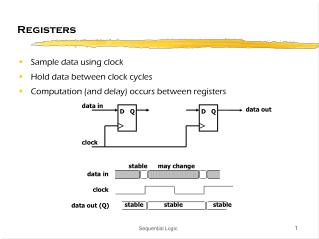
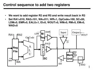
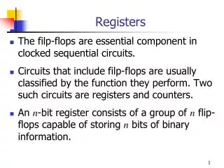
Control Registers • Intel386 DX has three control registers of 32 bits- CR0, CR2 and CR3 - to hold machine state of a global nature • These registers along with System Address Registers hold machine state that affects all tasks in the system • CR0 contains 6 defined bits for control and status purposes.
CR0 : Machine Control Register • The low-order 16 bits of CR0 is defined as Machine Status Word • To operate only on the low-order 16-bits of CR0, LMSW and SMSW instructions are used. • For 32-bit operations the system should use MOV CR0, Reg instruction.
CR0 : Machine Control Register • Bit 31 (PG Bit, Paging Enable) : The PG bit is set to enable the on-chip pagingunit. • Bit 4 (Reserved) : This bit is reserved by Intel.
CR0 : Machine Control Register • Bit 3 (TS Bit, Task Switched) : • TS is automatically set whenever a task switchoperation is performed. • Bit 2 (EM Bit, Emulate Coprocessor) : • This bit indicates whether coprocessor functions are to be emulated • If EM is set , the processor signals CoprocessorNot Available fault (exception 7).
CR0 : Machine Control Register • Bit 1 (MP Bit, Monitor Coprocessor) : • It indicates whether coprocessor is actually attached. • If , when executing a WAIT instruction CPU finds MP set, then it tests TS flag. • When both MP = 1 and TS= 1, the WAIT opcode signals exception 7. • Bit 0 (PE Bit, Protection Enable) : • The PE bit is set to enable the Protected Mode. • If PE is reset, the processor operates in Real Mode.
CR1 : Reserved • CR1 is reserved for use in future Intel processors
CR2 : Page Fault Linear Address • CR2 holds the 32-bit linear address that caused the last page fault detected.
CR3 : Page Directory Base Address • CR3 contains the physical base address of the page directory table. • The Intel386 DX page directory table is always page-aligned (4 Kbyte-aligned). • Thus the lowest twelve bits of CR3 are ignored. • A task switch through a TSS invalidates all page table entries in paging unit cache.