Download
1 / 24
270 likes | 322 Views
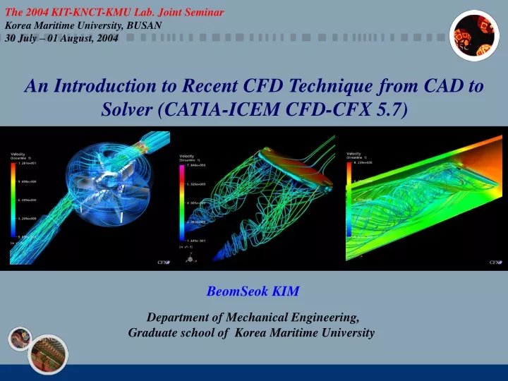
The 2004 KIT-KNCT-KMU Lab. Joint Seminar Korea Maritime University, BUSAN 30 July – 01 August, 2004. An Introduction to Recent CFD Technique from CAD to Solver (CATIA-ICEM CFD-CFX 5.7). BeomSeok KIM Department of Mechanical Engineering, Graduate school of Korea Maritime University.

E N D
The 2004 KIT-KNCT-KMU Lab. Joint Seminar Korea Maritime University, BUSAN 30 July – 01 August, 2004 An Introduction to Recent CFD Techniquefrom CAD to Solver (CATIA-ICEM CFD-CFX 5.7) BeomSeok KIM Department of Mechanical Engineering, Graduate school of Korea Maritime University
Procedure of General CFD Analysis Design CATIA, Solidworks, Pro-Engineer 3D Modeling Rough surface? Meshing Convergence problem? Coarse? – Quality check!! Solving Modification? Post-processing
Procedure of General CFD Analysis 3D Modeling CATIA, Solidworks, Pro-Engineer etc. ICEM-CFD 5.0, Grid Pro, Hyper Mesh etc. Meshing CFX-5.7, CFX-TASCflow, Fluent, Star-CD etc. Solving Post-processing AVS, Ensight, Field View, Amira etc.
3D-Modeling for Flow Meter : CATIA V5 R13 Casing Cover Guide Vain Rotor Shaft Guide Bearing Pivot Shaft Casing Inlet Filter
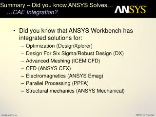
ICEM-CFD • ICEM: Integrated Computational Engineering and Manufacturing • CFD Version • Pre and Post Processor without Load, Constraint and Properties tabs. Includes Prism meshing. • Write mesh for 100+ CFD solvers. • - FSI • Combination of FEA and CFD features • Modernized and Integrated GUI • Wide CAD support • Mid-Plane Extractions/Extensions • Geometry Creation/Repair/Simplification Ref. : The 2004 International ANSYS Conference, Pittsburg, USA
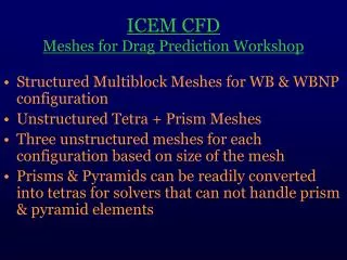
Powerful Meshing tools • Tetra from CAD, CAD and mesh, or mesh • Shell meshing, patch dependent, patch independent, mapped, structured/unstructured • Hex-dominant, unstructured hexa, structured hexa, extruded quads • Advanced mesh editing • Hexa Meshing Structured/Unstructured • Boundary Conditions • Output to 100+ Solvers • Post processing • Scriptable … and much more…
Solid Edge SolidWorks CATIA Pro/Engineer Unigraphics I-DEAS Wide CAD Support • 3rd Party Cad • IGES • ACIS • Parasolid • DWG/DXF • GEMS • Faceted Data • STL • VRML • NASTRAN, PATRAN, ANSYS, LS-DYNA
Tetra Meshing • Automatic Surface and Volume Meshing • Patch Independent • Surface mesh not required to generate volume mesh • Surface mesh can be saved independently • Very tolerant of imperfect geometry
Tetra Meshing • Most commercial Tet mesh generators • First generate a Tri surface mesh • surface-by-surface • Every edge of every surface must be resolved • sensitive to • sliver surfaces, • bad surface parameterization • surface connectivity (gaps) • If the surface mesh is complete • volume mesh is generated from surface mesh Mesh detail
Tetra Meshing • ICEM Tetra uses patch-independent, Octree method • Volume mesh • generated independent of surface model • Mesh is projected to model surfaces, curves and points • Surface mesh is created • Resulting mesh is independent of the underlying arrangement of surfaces Sliver ignored
Hexa Meshing • High-powered hexahedral grid generation • Top-down or Bottom-up blocking approach • Allows rapid creation of complex topologies • Fast Iteration Cycle • Elastic blocking can be fit to schematically similar geometry • Replay Files for parametric geometry changes
Hybrid Meshing • Prism layer • improve boundary layer resolution for tetrahedral mesh • Hex and Tet zones joined by a pyramid layer
Mesh Generation – Flow Meter • Inletpipe : 140,000 nodes • Outpipe : 100,000 nodes • Using Hybrid Mesh : Tetra - Prism • Complex Domain : Created by separately Inletpipe Prism Layer Outpipe
Mesh Generation – Flow Meter • Rotating Part : 510,000 nodes • Using Hybrid Mesh : Tetra - Prism • Complex Domain : Created by separately
Ref. :http://www.cfxkorea.com CFX-5.7 • Advanced coupled multigrid linear solver technology •Unmatched meshing flexibility •Superb parallel efficiency •Excellent pre and post-processing capabilities •A wide range of physical models that interoperate with each other providing real answers to industrial problems - Multiphase Flows - Bubbly Flows - Free Surface Flows - Particle Tracking - Mass Transfer : Cavitation, Boiling, Condensation, Evaporation
Boundary Conditions – Flow Meter Inlet : 0.4444kg/sec. GGI Grid Surface matching : Frozen Rotor Rotating : 800 rpm GGI Grid Surface matching : Frozen Rotor Outlet : Pressure (Averaged at Whole Surface)
= Grid Interface • Non overlap regions are created if interface sides do not fit perfectly (this should be avoided where possible) • Completely overlapping integration point faces • Partly non-overlapping integration point faces • Complete non-overlapping integration point faces • Slip walls are used at non-overlapping regions = Ref. :CFX-5.7 Basic Training Course, CFX-Korea
Interface Model : Frozen Rotor Compressor and Scroll Combined Tet and Hex mesh
Computation Results : Flow Meter • Velocity vector at mid-section • 3-D Clipping View • Velocity vector at inlet pipe • Velocity vector at out pipe • 720,000 node •Hybrid Mesh •Steady State/Frozen Rotor • RNG-KE/Water at 25 •Rotating Speed: 800RPM •Mass Flow-rate: 0.444kg/s
Computation Results : Flow Meter • Streamlines • Surface pressure • Calculated Torque at Rotating Blade : 0.0017592N M
Computation Results : Butterfly Valve • Computational Mesh Inlet Symmetry Outlet • 98,000 nodes • Hybrid Mesh : Tetra-Prism • RNG-KE/Steady State • Approaching Velocity : 3m/s • Water at 25
Computation Results : Butterfly Valve • Surface Pressure • Pipe Length : 2m • Isometric View • Diameter : 0.4m • Axis Symmetric Flow Field • Open Angle : 45 deg.
Computation Results : Butterfly Valve • Stream Lines from Inlet to Outlet • Stream Lines behind Valve Plate • Calculated Torque at V/V Plate : 30.4568 N M • Surface Pressure • Velocity Vector