Download
1 / 13
130 likes | 190 Views
Physics 2102 Jonathan Dowling. Lecture 28. Ch. 35: Interference. A red light beam with wavelength l =0.625 m m travels through glass (n=1.46) a distance of 1mm. A second beam, parallel to the first one and originally in phase with it, travels the same distance through sapphire (n=1.77).

E N D
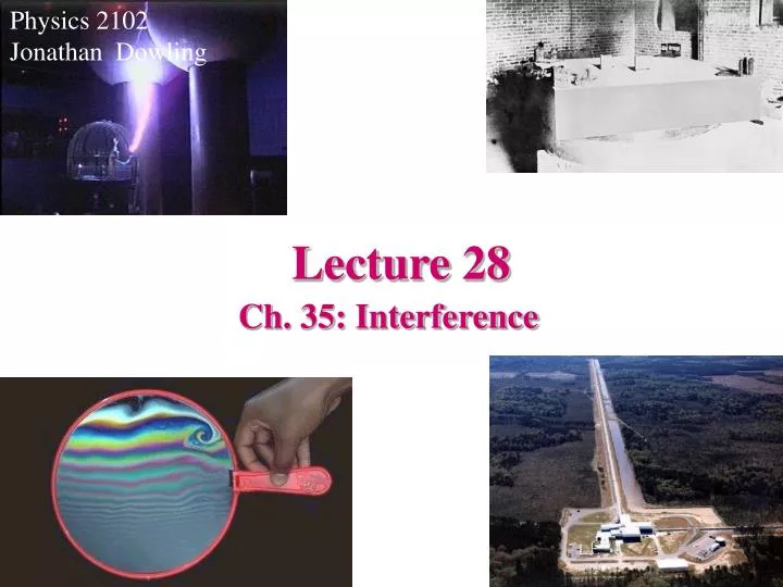
Physics 2102 Jonathan Dowling Lecture 28 Ch. 35: Interference
A red light beam with wavelength l=0.625mm travels through glass (n=1.46) a distance of 1mm. A second beam, parallel to the first one and originally in phase with it, travels the same distance through sapphire (n=1.77). Interference: Example • How many wavelengths are there of each beam inside the material? • In glass, lg=0.625mm/1.46= 0.428 mm and Ng=D/ lg=2336.45 • In sapphire, ls=0.625mm/1.77= 0.353 mm (UV!) and Ns=D/ ls=2832.86 • What is the phase difference in the beams when they come out? • The difference in wavelengths is Ns-Ng=496.41. Each wavelength is 360o, so DN=496.41 means Df=DNx360o=0.41x360o=148o • How thick should the glass be so that the beams are exactly out of phase at the exit (destructive interference!) • DN=D/ ls- D/ lg= (D/ l)(n2-n1)=0.31 (D/ l)=m+1/2 • A thickness D=(m+0.5) 2.02 mm would make the waves OUT of phase. • For example, 1.008 mm makes them in phase, and 1.010 mm makes them OUT of phase.
Thin Film Interference: The patterns of colors that one sees in oil slicks on water or in bubbles is produced by interference of the light bouncing off the two sides of the film. To understand this we need to discuss the phase changes that occur when a wave moves from one medium to the another where the speed is different. This can be understood with a mechanical analogy.
Reflection, Refraction and Changes of Phase: Consider an UP pulse moving in a rope, that reaches a juncture with another rope of different density. A reflected pulse is generated. The reflected pulse is also UP if the speed of propagation in the rope of the right is faster than on the left. (Low impedance.) The reflected pulse is DOWN if the speed of propagation in the right is slower than on the left. (High impedance.) The extreme case of ZERO speed on the right corresponds to a rope anchored to a wall. (Highest impedance.) If we have a wave instead of a pulse “DOWN” means 180 degrees OUT of phase, and UP means 360° or IN PHASE.
Thin Films First reflected light ray comes from first interface, second from second. These rays interfere with each other. n1 n2 n3 How they interfere will depend on the relative indices of refraction. In the example above the first ray suffers a 180 degree phase change (1/2 a wavelength) upon reflection. The second ray does not change phase in reflection, but has to travel a longer distance to come back up. The distance is twice the thickness of the layer of oil. For constructive interference the distance 2L must therefore be a half-integer multiple of the wavelength, i.e. 0.5 l, 1.5 l,…,(0.5+2n)l.
Thin Films: Soap Bubbles If the film is very thin, then the interference is totally dominated by the 180° phase shift in the reflection. At the top the film is thinnest (due to gravity it lumps at the bottom), so one sees thefilm dark at the top. 180° 0° Air: n=1 Soap: n>1 Air This film is illuminated with white light, therefore we see fringes of different colors corresponding to the various constructive interferences of the individual components of the white light, which change as we go down. The thickness increases steeply as we go down, which makes the width of the fringes become narrower and narrower.
n=2.35 n=1.38 Reflective Coatings To make mirrors that reflects light of only a given wavelength, a coating of a specific thickness is used so that there is constructive interference of the given wavelength. Materials of different index of refraction are used, most commonly MgFe2 (n=1.38) and CeO2 (n=2.35), and are called “dielectric films”. What thickness is necessary for reflecting IR light with l=1064nm? First ray: Df=180deg=p Second ray: Df=2L(2p/(l/n))=p => L= lCeo2/4=(l/n)/4=113nm Third ray? If wafer has the same thickness (and is of the same material), Df=4L(2p/(l/n)=2p: destructive! Choose MgFe2 wafer so that Df=(2n1L1+2n2L2) (2p/l)= p+ 2n2L2 (2p/l)=3p => L2= l/2n2 = 386 nm We can add more layers to keep reflecting the light, until no light is transmitted: all the light is either absorbed or reflected.
Anti-Reflective Coatings Semiconductors such a silicon are used to build solar cells. They are coated with a transparent thin film, whose index of refraction is 1.45, in order to minimize reflected light. If the index of refraction of silicon is 3.5, what is the minimum width of the coating that will produce the least reflection at a wavelength of 552nm? Both rays undergo 180 phase changes at reflection, therefore for destructive interference (no reflection), the distance travelled (twice the thickness) should be equal to half a wavelength in the coating n=1.45
Anti-Reflective Coatings Radar waves have a wavelength of 3cm. Suppose the plane is made of metal (speed of propagation=0, n is infinite and reflection on the polymer-metal surface therefore has a 180 degree phase change). The polymer has n=1.5. Same calculation as in previous example gives, Stealth Fighter On the other hand, if one coated a plane with the same polymer (for instance to prevent rust) and for safety reasons wanted to maximize radar visibility (reflective coating!), one would have
Michelson Interferometers: As we saw in the previous example, interference is a spectacular way of measuring small distances (like the thickness of a soap bubble), since we are able to resolve distances of the order of the wavelength of the light (for instance, for yellow light, we are talking about 0.5 of a millionth of a meter, 500nm). This has therefore technological applications. In the Michelson interferometer, light from a source (at the left, in the picture) hits a semi-plated mirror. Half of it goes through to the right and half goes upwards. The two halves are bounced back towards the half plated mirror, interfere, and the interference can be seen by the observer at the bottom. The observer will see light if the two distances travelled d1 and d2 are equal, and will see darkness if they differ by half a wavelength.
Michelson-Morley Experiment Michelson won the Nobel prize in 1907, "for his optical precision instruments and the spectroscopic and metrological investigations carried out with their aid" "The interpretation of these results is that there is no displacement of the interference bands. ... The result of the hypothesis of a stationary ether is thus shown to be incorrect." (A. A. Michelson, Am. J. Sci, 122, 120 (1881))
The largest Michelson interferometer in the world is in Livingston, LA, in LSU owned land (it is operated by a project funded by the NationalScience Foundation run by Caltech and MIT, and LSU collaborates in the project). Mirrors are suspended with wires and will move detecting ripples in the gravitational field due to astronomical events. http://www.ligo-la.caltech.edu
TAMA (Japan)Mitaka VIRGO (French-Italian) Cascina, Italy AIGO (Australia), Wallingup Plain, 85km north of Perth Gravitational Waves Interferometry:an International Dream GEO600 (British-German) Hannover, Germany LIGO (USA) Hanford, WA and Livingston, LA