Download
1 / 87
880 likes | 1.06k Views
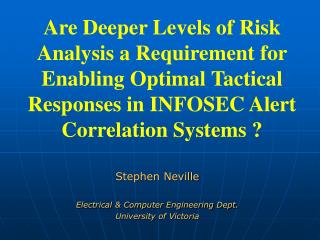
Sigma Xi Guest Lecture February 27, 2002 Survivable Networks: Protecting the Internet and phones from “backhoe-fades” and other hazards. Wayne D. Grover University of Alberta, Dept. of Electrical & Computer Engineering TR Labs , Network Systems Group. Outline (selected topics). Background

E N D
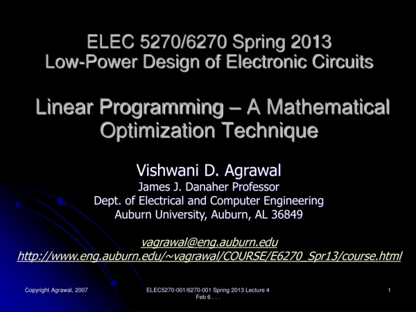
Sigma Xi Guest Lecture February 27, 2002Survivable Networks: Protecting the Internet and phones from “backhoe-fades” and other hazards Wayne D. Grover University of Alberta, Dept. of Electrical & Computer Engineering TRLabs, Network Systems Group
Outline (selected topics) • Background • Fiber Optics, DWDM, • Multiplexing & Concept of a Transport Network • Goals and Impacts of Protection / Restoration times • Rings • types • multi-ring network design • Span-restorable mesh • concept, self-organizing approach • capacity design • Path-restorable networks • p-cycles • Some Current Research
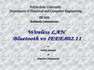
US Circuit Switched Voice and Internet Traffic Source: Renaissance Analysisvia Marconi PLC 2001 CAGR 1996-2005 14,000 12,000 Internet 95.8% 10,000 8,000 Terabytes / day Voice over IP 30% 6,000 Data Traffic 30% 4,000 2,000 Circuit Switched 12.1% 0 1996 1997 1998 1999 2000 2001 2002 2003 2004 2005
1310nm 1550nm 0.6 0.5 0.4 Attenuation (dB/km) 0.3 0.2 0.1 1500 1600 1700 1400 1300 1200 Fiber Optics and WDM: Wavelength (nm)
Dense WDM: ITU Channel Spacing ITU Channel Spacing 0.6 1540 1530 1535 1545 1550 1555 1560 1565 1525 0.5 0.4 And each wavelength can carry ~ OC-192 (10 Gb/s) Attenuation (dB/km) 0.3 0.2 0.1 1500 1600 1700 1400 1300 1200 Wavelength (nm)
How important is one little fiber? Adapted from Marconi OctoBrief 2001 If 64Kb/s = 1 lane Then Based on Current Technology, a single Fiber would = 25 Million Lanes, or a Highway that was 60,000 Miles Wide
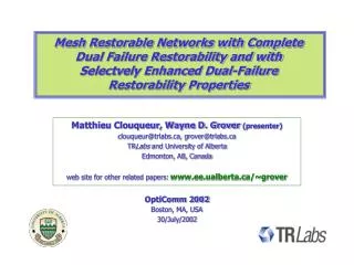
some real network topologies 32-node Italian backbone transportnetwork
some real network topologies Belgiannational transportnetwork (Belga 39 - 39 nodes, 59 spans)
some real network topologies “COST 239” European Communityproject model ( 19 nodes, 40 spans)
some real network topologies “MCI” North Americancontinental backbone (disguisedtopology only)
So everything is fine until.... “ Universal Cable Locator “ !!
News Reports • Massive fiber cuts interrupt Net traffic • "Let me tell you, it really hurts right now," said AboveNet's chief technology officer. "We were given a 1 hour estimate for this problem to be corrected." • SEA-ME-WE3 cable cut again • The cable was damaged by sand-mining operations in Indonesian territorial waters about 50 kilometers south of Singapore. International traffic from Australia was seriously affected. • Massive Fiber Cut Pauses East-West Traffic • A fiber-optic cable cut in Ohio interrupted all forms of traffic across the United States for nearly 12 hours Wednesday has been repaired. ... four OC-192 lines that were accidentally severed by a gas company employee digging with a backhoe.
Severe Business Impact: Regulatory reporting Service Impact of failure duration TCP Session timeout, X25 disconnect Impact (Log scale) No impact, TCP recovers, Reframe Application timeout, Business Impact TCP re-transmit, minor delays, Some voice calls dropped, Video degradation Service Impact Severity No impact, TCP recovers, 5% Voice disconnect TCP Backoff, unfairness, User terminates session, All voice calls lost Business Impact 0.01 0.1 1 10 100 1K 10K Time (sec) 50 - 150 ms 100s of ms 10sec to mins 15 min to 30 min Target range 2 sec : all circuit-switched connections dropped
Concept of a “transport network” End-users Service layer Logical layer system Physical layer geographical
Network Layers San Francisco New York Logical Trunk Group of n x DS1 Switch Switch Service Layer n x DS3 DCS OCn Transport Layer
Concept of a transport network: one physical network - billions of logical network possibilities…through cross-connects
Optical cross-connect Optical transport system (1.55 mm) Optical transport system (1.55 mm) l-Mux ... ... Optical-layer Cross-connect (Optical or Electronic Fabric) ... ... Fibers In Fibers Out ... ... Transparency = node-bypass ... ... ... ... Drop ports Add ports
Source: L-Y. Lin (AT&T) Optical Layer SwitchingAn 8x8 Switch Chip size: 1 cm x 1 cm
Each layer has a native form of “demand units” that are aggregated into capacity units of the next lower layer Erlangs, packets, private lines, ATM VCs End-users Service layer #s of: DS-0, DS-1, VPs, STS-n(PL), STSn(IP) Logical layer #s of: OC-48, OC-192, wavelengths “the transportnetwork” system #s of fibers, wavelength regens, add-drop Physical layer geographical #s of cables, ducts, transponders, spectral allocations
(APS systems) 1+1 1:1 1:N -> rings UPSR: unidirectional path switched rings BLSR: bi-directional line-switched rings -> mesh span - restorable path - restorable (shared backup path protection) -> p-cycles (ring-mesh hybrids) based on access / core principles based on forcer clipping principle Some basic approaches to network survivability …
Two main types of “survivable ring”.... UPSR Unidirectional Path-switched Ring ... Unidirectional - because in normal operation all working demand flows in one direction only. i.e., A sends to B clockwise, B also sends to A clockwise Path-switched- because in restoration each receiver selects an alternate end-to-end paththrough ring, regardless of whereactual break occurred.
UPSR Animation... Working fibre 1 Tail-end Switch 5 2 Protection fibre 3 4 l1
UPSR (OPPR) ...line capacity requirement A -> B A • Consider a bi-directional demand quantity between nodes A, B: dA,B.- A to B may go on the short route- then B to A must go around the longer route • Thus, every (bi-directional) demand paircircumnavigates the entire ring. • Hence in any cross section of the ring,we would find one unidirectional instanceof every demand flow between nodes of the ring. • Therefore, the line capacity of the UPSRmust be: E B B -> A C D “ The UPSR must have a line rate (capacity) greater (or equal to)the sum of all the (bi-directional)demand quantities between nodes of the ring. “
Two main types of “survivable ring”.... BLSR Bi-directional Line-switched Ring...Principle of operation (“4-fibre” BLSR illustrated) Bi-directional - because in normal operation working demand flows travel in opposite directions over the sameroute through the ring Line-switched- because in restoration the compositeoptical line transmission signal is switched to the other direction around the ring (on the other fibre pair)specifically around the failed section.
(4 fibre) BLSR Animation... Working fibres 1 Loop-back 5 2 Protection fibres 3 4 l1 Loop-back
BLSR …(OPSR) line capacity requirement • both directions of a bi-directional demand can follow the short (or long) route between nodes • “Bandwidth reuse” • The line capacity of the BLSR must be: • Planning issues / inefficiencies: • better than UPSR for non-hubbed • capacity dependence on demand pattern • “stranded capacity” • span exhaust A -> B A B -> A E B C D “ The BLSR must have a line rate (capacity) greater (or equal to)the largest sum of demands routedover any one span of the ring. “
Effect of some demand patterns on BLSR • From preceding it is evident that BLSR demand-serving ability depends in general on the demand pattern. • Some of the recognized tendencies in real demand patterns are: same basic “access” demand pattern but dual hubs employedfor access survivability or “mesh” this is thegeneral tendency in inter-city backbonenetwork optimization of ring loading ideal case for BLSRperfect bw re-use BLSR much moreefficient than UPSR no optimization required this is a fairly exact model for access ring applications BLSR efficiency = UPSR
Effectiveness of BLSR relative to UPSR depends on demand pattern with perfect bw re-useBLSR gets proportionallybetter as ring size increases in this range optimized BLSR loading (and ring selection)can give significant benefitsover UPSR Total demand serving capability with perfect hubbing demand patterns, BLSR never has any advantage over UPSR
BLSR related optimization problems • 1. Ring “Sizing” • - CONTEXT: A number of demand pairs are to be served by a BLSR • - QUESTION IS: What is the minimum line rate BLSR required? Required BLSRline capcity • line rate = f (demands, routing in ring) Q. What is it that has to be optimallydecided to minimize the required line rate ? i.e. (What do we have control over here?) demands that mustbe served A. for each demand: cw, or ccw ?
BLSR related optimization problems • 2. Ring “Loading” • - CONTEXT: A number of demand pairs are to be served, but not necessarily all in same ring. • i.e., there is a “pool” of outstanding demands to consider for selection into a given ring. • - QUESTION IS: What is the maximum number of these demands that a BLSR with given capacity can serve? • or... (alternate goal) • Which set of demands (and routings) achieves greatest utilization of ring capacity? fixed ringcapacity pool of demandsneeding to be served ? which demandsto pick ?
Given • Network topology • Demand pattern • Ring types • Cost model Subject to: • All demands served • Capacity constraints • Max. ADMs per ring • Inter-ring transit locations • Partial add/drop constraints • Matched-nodes requirements, etc. Multi-Ring Network Design Problem Min-cost Design Design Method • Ring Systems • Type • OC-n size • Topological layout • Glass-through locations • Routing • Ring assignment • Inter-ring transit locations
On the complexity of multi-ring design • Upper bound on number of ring candidates for each graph cycle: • Every combination of 2, 3, 4....up to N nodes defines a prospective collectionof active ADM nodes that could be grouped together to define one ring. • Upper bound on the number of different multi-ring designs that exist: • Every combination of 1, 2, 3, 4....up to some pre-determined maximumnumber of rings can be considered as a multi-ring design solution.. and ... also multiply by the number of “ring technologies” being considered.
Question: How big is ? illustration: a 10 node network: 1013 possible rings, 1021 possible multi-ring networks (over 100 million years to evaluate all designs at 10 6 design evaluations / sec.) !
Concepts and principles in multi-ring design • Concept (each follows in more detail): • graph coverage: • Balance • Capture • Span elimination • Dual-ring interconnect • transit sites • glass-throughs ....a set of rings that covers every edge of the graph. This is one class of ring network. ....in a BLSR, how well are the wiquantities “balanced” ? (sincethe largest of them dictates the protection capacity). ....to what extent does a given ring tend to serve demands that both originate and terminate in the same ring. ....a multi-ring design may not “cover” all graph edges, if the working demands can take non-shortest path routes. ....for the highest service availability, some demands may employ geographically redundant duplicate inter-ring transfers ....not all nodes may be sites where demands can switch rings. ....each ring needs ADMs where demands add / drop, but not elsewhere ( ~> Express rings etc.).
“Graph coverage” and concept of span elimination • a set of rings that uses or overlies all edges of the physical facilities graph is called a “ring cover”. • “Coverage-based” design is a special (simpler) case of multi-ring design. “span eliminations” example a single ring design that may also serve alldemands a three ring “cover”
Concept of dual-ring interconnect (DRI) “drop-and-continue” method for BLSRs (also called Matched Nodes arrangement) the primary gateway node has a 1+1 receive selection setup here. protected byBLSR line-loopbackreaction in r1 protected by1+1 APS inter-ringsetup protected byBLSR line-loopbackreaction in r2
Ring Connectivity Graph (RCG) for routing through ring networks • RCG is a transformation of the graph that represents the opportunities to transition from ring to ring. • example: with ring-set given, r1 is connected to r2 through only one node. • For DRI routing, only the RCG edges with 2 or more parallel arcs are available for routing
Some Mathematical Tools and Approaches to multi-ring network design • SCIP = “span coverage IP” * • Fixed charge and routing model • Modular aggregating routing * • Iterated greedy ring placement * • Eulerian decomposition • demand re-packing * • Hierarchical Rings • Tabu Search * • * = techniques used in combination in RingBuilder™
State of the art and Research Directions in Multi-Ring Network Design Capacitated Multi-technology Multi-period • Probabilistic • Topology Tabu Search (Morley,Grover, ‘01) Ring Coverage IP (Kennington, ‘97). Solution Quality Research Goals Eulerian Ring Covers(Gardner et al., ‘94). RingBuilder™ (Slevinsky,Grover, ‘93) RingBuilder™ (Slevinsky,Grover, ‘95) Simulated Annealing(Roberts, ‘94). Net-Solver (Gardner et al., ‘95) Hierarchical Rings (Shi,Fonseka, ‘96). Strategic Options (Wasem,Wu ‘91) Model Accuracy
The concept and vision of distributed mesh restoration • on-line simulation of “Selfhealing network” Tellium Corp. • Key attributes: • sharing of spare capacity over failure scenarios • completely adaptive to current network state (network is the database) • real time ( << 1 second) • assurances of 100% restorability with theoretical minimum of spare capacity • self-monitoring • no central control (except for oversight) • no global view databases of network state required • no conventional inter-nodal signalling protocols; “self-organizing”
SHN Protocol Overview The SHN protocol is an event-driven finite state machine (FSM) • Node states: • Pre-failure state • Sender state -----------> multi-index “forward flooding” • Chooser state ----------> initiates reverse linking / index • Tandem node state ---> forward flood competition • ---> reverse linking, cross-connection • Key concept of a “statelet” • not inter-processor messaging • fixed fields, channel associated • space / location encodes problem information
SHN Tandem Nodes Rules 1) Keep list of ports where precursor statelets are presently found and sort statelets by: • increasing repeat count • increasing number of the port where they appear 2) Replace precursors by better ones when better ones appear 3) Try as much as possible to re-broadcast statelets to all other spans 3a) When full re-broadcast is not possible, consider statelets in order of repeat count starting with the lowest values. 4) When complement statelet is received it is copied to the port of the precursor, all re-broadcast of forward flooding statelets for the corresponding index is stopped and a cross-connection is made • After any of these eventsthe rebroadcast pattern is revised to follow rule 3