Download

1 / 38
410 likes | 1.35k Views
Stereo Vision using PatchMatch Algorithm. Junkyung Kim Class of 2014. 1 . Reference. Reference. Primary PatchMatch : A Randomized Correspondence Algorithm (Barnes et al, PAR 2009) Secondary A Computational Theory of Human Stereo Vision (Marr & Poggio , 1979)

E N D
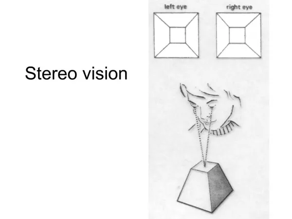
Stereo Vision using PatchMatch Algorithm Junkyung Kim Class of 2014
Reference • Primary • PatchMatch : A Randomized Correspondence Algorithm (Barnes et al, PAR 2009) • Secondary • A Computational Theory of Human Stereo Vision (Marr & Poggio, 1979) • PatchMatch Stereo - Stereo Matching with Slanted Support Windows (Bleyer, Rhemann, and Rother, BMVC 2011) • Dataset • Middlebury Dataset (later)
Summary of Work • Implemented PatchMatch stereo in MATLAB • Implemented additional features • Ability to constrain search space by disparity • Ability to use weighted distance measure • Min-Distance minimization* • Performed comprehensive evaluation
Evaluation • How evaluation is done • Dataset • Middlebury 2006 dataset • Hiebert-Treueret al, CVPR 2007 • 21 binocular stereo images • Used sixth-size images • half of third-size images provided : 413~465 x 370
Evaluation • How evaluation is done • Parameter-wise evaluation • Focused on the performance (accuracy) gain / loss across different parameter dimensions • To account for rate of convergence, took 3-iteration output for every configuration.
Evaluation • How evaluation is done • Measure of error • Squared error of output disparity map from ground-truth disparity map. • Sum(sum((GroundTruth – Output).^2)) • Took average error across 21 images, along with +,- two standard deviations
Evaluation • 1. Propagation stage • Built-in PatchMatchfeature • Takes advantage of smoothness constraint • Does not enforce it
Evaluation • 2. Constrained search space • Avoids possible false local minima • Maybe useful for fixed-camera applications
PatchMatch on Stereo Black : Baseline Green : Constrained disp, propagation off Blue : Constrained disp, propagation on Red : Exhaustive Search
Evaluation • 3. Patch size • Built-in PatchMatch feature • Smaller Patch size • Less smoothness enforced • Smaller sample space • Larger Patch size • Generally leads to more accuracy • Does not work for non-frontoparallel space • Does not work for locations of depth discontinuity
Evaluation • 3. Representation : RGB • Baseline : Grayscale • Increase selectivity
Evaluation • 3. Representation : Filtered output • Filter : Derivative of Gaussians • “Edge detectors” • One scale (11), two phases, 6 orientations • Tradeoff : heavier computational load • times O(# of filters)
Evaluation • 3. Representation : Filtered output • Improved performance in certain range of patch sizes • Trying multiscale oriented DoG’s will probably improve performance further • Might increase error at locations with high orientation disparity
Evaluation • 3. Representation : Filtered output • Orientation disparity is mostly limited to highly horizontally slanted surfaces • Even in those cases, the effect is not very significant, given small ratio of binocular distance to the distance from the camera to the surface
Evaluation • 3. Representation : Filtered output • Orientation disparity is mostly limited to highly horizontally slanted surfaces • Even in those cases, the effect is not very significant, given small ratio of binocular distance to the distance from the camera to the surface
Evaluation • 4. Support : Gaussian Mask • Baseline : uniform, square window • ‘loosens’ the assumption on frontoparallel surface by differentially decreasing weight as you move away from the center.
Evaluation • Limitations • Every surface might require different support. • Gaussian should be elongated orthogonal to the direction of slant. • Problem is, we need a way for the system to figure out which. • Symmetric masks can’t capture the correct surface constraints at surface discontinuity • Can be ideally solved by graph-cuts, but impossible under PatchMatch framework.
Evaluation • 4. Support : Min-minimization • Slightly different approach to masking method. • Instead of one, compute distance using multiple masks of different shapes (normalized), each reflecting different surface configuration in support window • Pick the minimum distance (presumably the one computed using the ‘correct’ surface support) • I used half-rectified Gabors • To avoid bias, I applied CS gaussian over each mask • Again, the problem is multiplied computational time
Evaluation • Reduced error the most • Small increase in variance • High increase in computation time