Download
1 / 48
480 likes | 598 Views
E-166 Undulator-Based Production of Polarized Positrons A proposal for the 50 GeV Beam in the FFTB Thursday, June 12, 2003 K-P. Sch ü ler and J. C. Sheppard. Undulator-Based Production of Polarized Positrons. E-166 Collaboration. (45 Collaborators).

E N D
E-166Undulator-Based Production of Polarized PositronsA proposal for the 50 GeV Beam in the FFTBThursday, June 12, 2003K-P. Schüler andJ. C. Sheppard
Undulator-Based Production of Polarized Positrons E-166 Collaboration (45 Collaborators)
Undulator-Based Production of Polarized Positrons E-166 Collaborating Institutions (15 Institutions)
E-166 Experiment E-166 is a demonstration of undulator-based polarized positron production for linear colliders - E-166 uses the 50 GeV SLAC beam in conjunction with 1 m-long, helical undulator to make polarized photons in the FFTB. - These photons are converted in a ~0.5 rad. len. thick target into polarized positrons (and electrons). - The polarization of the positrons and photons will be measured.
The Need for a Demonstration Experiment Production of polarized positrons depends on the fundamental process of polarization transfer in an electromagnetic cascade. While the basic cross sections for the QED processes of polarization transfer were derived in the 1950’s, experimental verification is still missing
The Need for a Demonstration Experiment Each approximation in the modeling is well justified in itself. However,the complexity of the polarization transfer makes the comparison with experiment important so that the decision to build a linear collider w/ or w/o a polarized positron source is based on solid ground. Polarimetry precision of 5% is sufficient to prove the principle of undulator based polarized positron production for linear colliders.
Physics Motivation for Polarized Positrons Polarized e+ in addition to polarized e- is recognized as a highly desirable option by the WW LC community (studies in Asia, Europe, and the US) Having polarized e+ offers: • Higher effective polarization -> enhancement of effective luminosity for many SM and non-SM processes, • Ability to selectively enhance (reduce) contribution from SM processes (better sensitivity to non-SM processes, • Access to many non-SM couplings (larger reach for non-SM physics searches), • Access to physics using transversely polarized beams (only works if both beams are polarized), • Improved accuracy in measuring polarization.
Physics Motivation: An Example Separation of the selectron pair in with longitudinally polarized beams to test association of chiral quantum numbers to scalar fermions in SUSY transformations
NLC/USLCSG Polarized Positron System Layout 2 Target assembles for redundancy
E-166 Vis-à-vis a Linear Collider Source E-166 is a demonstration of undulator-based production of polarized positrons for linear colliders: - Photons are produced in the same energy range and polarization characteristics as for a linear collider; -The same target thickness and material are used as in the linear collider; -The polarization of the produced positrons is expected to be in the same range as in a linear collider. -The simulation tools are the same as those being used to design the polarized positron system for a linear collider. - However, the intensity per pulse is low by a factor of 2000.
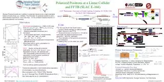
E-166 Beamline Schematic 50 GeV, low emittance electron beam 2.4 mm period, K=0.17 helical undulator 0-10 MeV polarized photons 0.5 rad. len. converter target 51%-54% positron polarization
E-166 Helical Undulator Design, l=2.4 mm, K=0.17 PULSED HELICAL UNDULATOR FOR TEST AT SLAC THE POLARIZED POSITRON PRODUCTION SCHEME. BASIC DESCRIPTION. Alexander A. Mikhailichenko CBN 02-10, LCC-106
Helical Undulator Radiation Circularly Polarized Photons
Polarized Positrons from Polarized g’s Circular polarization of photon transfers to the longitudinal polarization of the positron. Positron polarization varies with the energy transferred to the positron. (Olsen & Maximon, 1959)
Polarized Positron Production in the FFTB Polarized photons pair produce polarized positrons in a 0.5 r.l. thick target of Ti-alloy with a yield of about 0.5%. Longitudinal polarization of the positrons is 54%, averaged over the full spectrum Note: for 0.5 r.l. W converter, the yield is about 1% and the average polarization is 51%.
Polarimetry K-Peter Schüler Presentation
Polarimeter Overview 4 x 10⁹ 4 x 10⁷ 1 x 10¹⁰ e- 4 x 10⁹ 4 x 10⁹ 2 x 10⁷ e+ 4 x 10⁵ e+ 1 x 10³ 2 x 10⁷ e+ 4 x 10⁵ e+
M. Goldhaber et al. Phys. Rev. 106 (1957) 826. Transmission Polarimetry of (monochromatic) Photons all unpolarized contributions cancel in the transmission asymmetry (monochromatic case)
Transmission Polarimetry of Photons Monochromatic Case Analyzing Power: But, undulator photons are not monochromatic: Must use number or energy weighted integrals
Transmission Polarimetry of Positrons 2-step Process: • re-convert e+ via brems/annihilation process • polarization transfer from e+ to proceeds in well-known manner • measure polarization of re-converted photons with the photon transmission methods • infer the polarization of the parent positrons from the measured photon polarization Experimental Challenges: • large angular distribution of the positrons at the production target: • e+ spectrometer collection & transport efficiency • background rejection issues • angular distribution of the re-converted photons • detected signal includes large fraction of Compton scattered photons • requires simulations to determine the effective Analyzing Power Formal Procedure: Fronsdahl & Überall; Olson & Maximon; Page; McMaster
Spin-Dependent Compton Scattering • Simulation with modified GEANT3 • (implemented by V. Gharibyan) • standard GEANT is unpolarized • ad-hoc solution: • - substitute unpolarized Compton subroutines • with two spin-dependent versions (+1 and -1) • and run these in sequence for the same • same beam statistics • - then determine analyzing power from this data
Analyzer Magnets g‘ = 1.919 0.002 for pure iron, Scott (1962) Error in e- polarization is dominated by knowledge in effective magnetization M along the photon trajectory: active volume Photon Analyzer Magnet: 50 mm dia. x 150 mm long Positron Analyzer Magnet: 50 mm dia. x 75 mm long
Photon Polarimeter Detectors E-144 Designs: Si-W Calorimeter Threshold Cerenkov (Aerogel)
Positron Transport System e+ transmission (%) through spectrometer photon background fraction reaching CsI-detector
CsI Calorimeter Detector Crystals: from BaBar Experiment Number of crystals: 4 x 4 = 16 Typical front face of one crystal: 4.7 cm x 4.7 cm Typical backface of one crystal: 6 cm x 6 cm Typical length: 30 cm Density: 4.53 g/cm³ Rad. Length 8.39 g/cm² = 1.85 cm Mean free path (5 MeV): 27.6 g/cm² = 6.1 cm No. of interaction lengths (5 MeV): 4.92 Long. Leakage (5 MeV): 0.73 % Photodiode Readout (2 per crystal): Hamamatsu S2744-08 with preamps
Expected Photon Polarimeter Performance Si-W Calorimeter Expected measured energy asymmetry δ = (E+-E-)/(E++E-) and energy-weighted analyzing power determined through analytic integration and, with good agreement, through special polarized GEANT simulation Energy-weighted Mean Aerogel Cerenkov will measureP for E > 5 MeV (see Table 12) 1% stat. measurements very fast (~ minutes), main syst. error of ΔP /P ~ 0.05 from Pe
Expected Positron Polarimeter Performance I Simulation based on modified GEANT code, which correctly describes the spin-dependence of the Compton process Number- & Energy-Weighted Analyzing Power vs. Energy Photon Spectrum & Angular Distr. 10 Million simulated e+ per point & polarity on the re-conversion target
Expected Positron Polarimeter Performance II Analyzing Power vs. Energy Spread Analyzing Power vs. Target Thickness
Polarimetry Summary • Transmission polarimetry is well-suited for photon and positron beam measurements in E166 • Analyzing power determined from simulations is sufficiently large and robust • Measurements will be very fast with negligible statistical errors • Expect systematic errors of ΔP/P ~ 0.05 from magnetization of iron
Beam Request J. C. Sheppard Presentation II
E-166 Beam Request • 6 weeks of activity in the SLAC FFTB: • 2 weeks of installation and check-out • 1 week of check-out with beam • 3 weeks of data taking: • roughly 1/3 of time on photon measurements, 2/3 of time on positron measurements.
E-166 Beam Measurements • Photon flux and polarization as a function of K • (Pg~ 75% for Eg > 5 MeV). • Positron flux and polarization for K=0.17, 0.5 r.l. of Ti vs. energy. (Pe+~ 50%). • Positron flux and polarization for 0.1 r.l. and 0.25 r.l. Ti and 0.1, 0.25, and 0.5 r.l. W targets. • Each measurement is expected to take about 20 minutes. • A relative polarization measurement of 5% is sufficient to validate the polarized positron production processes.
E-166 as Linear Collider R&D • E-166 is a proof-of-principle demonstration of undulator based production of polarized positrons for a linear collider. • The hardware and software expertise developed for E-166 form a basis for the implementation of polarized positrons at a linear collider.
E-166 Costs Experiment E-166_attach1-052703.xls (J. Weisend, E-166 Impact Report) (All entries in k$)
E-166 Institutional Responsibilities Experiment E-166_attach1-052703.xls(J. Weisend, E-166 Impact Report) (All entries in k$)
(polarimetry extra) Undulator Photon Beam I Undulator basics (1st harmonic shown only) E166 undulator parameters
(polarimetry extra) Undulator Photon Beam II photon spectrum, angular distribution and polarization
(polarimetry extra) Positron Beam Simulation distributions behind the converter target (0.5 r.l. Ti) based on polarized EGS shower simulations by K. Flöttmann
(polarimetry extra) Low-Energy Polarimetry Candidate Processes • Photons: Compton Scattering on polarized electrons • forward scattering (e.g. Schopper et al.) • backward scattering • transmission method (e.g. Goldhaber et al.) • Positrons: all on ferromagnetic = polarized e- targets • Annihilation polarimetry (e+e- ) (e.g. Corriveau et al.) • Bhabha scattering (e+e- e+e-) (e.g. Ullmann et al.) • brems/annihilation (e+ ) plus -transmission (Compton) polarimetry
(polarimetry extra) Trade-offs Principal difficulties of e+ polarimetry: • huge multiple-scattering at low energies even in thin targets • cannot employ double-arm coincidence techniques or single-event counting due to poor machine duty cycle • low energies below 10 MeV, vulnerable to backgrounds All of the candidate processes have been explored by us: • the transmission method is the most suitable
(polarimetry extra) Compton Cross Section
(polarimetry extra) e+ polarimeter: typical GEANT output (example) I
e+ polarimeter: typical GEANT output (example) II (polarimetry extra) * * Assuming 2 x 10⁵ e+ per pulse (1% e+ spectrometer transmission)