Download
1 / 16
170 likes | 179 Views
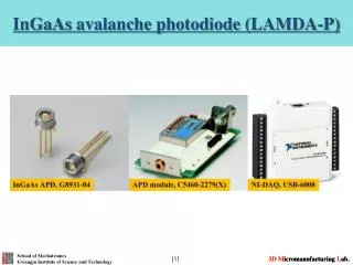
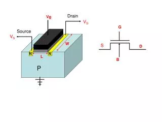
InGaAs MOSFET with self-aligned Source/Drain by MBE regrowth. Uttam Singisetti*, Mark A. Wistey, Greg J. Burek, Erdem Arkun, Ashish K. Baraskar, Brian J. Thibeault, C. J. Palmstr ø m, A.C. Gossard, and M.J.W. Rodwell ECE and Materials Departments

E N D
InGaAs MOSFET with self-aligned Source/Drain by MBE regrowth Uttam Singisetti*, Mark A. Wistey, Greg J. Burek, Erdem Arkun, Ashish K. Baraskar, Brian J. Thibeault, C. J. Palmstrøm, A.C. Gossard, and M.J.W. Rodwell ECE and Materials Departments University of California, Santa Barbara, CA, USA Yanning Sun, Edward W. Kiewra, and D.K. Sadana IBM T J Watson Research Center, Yorktown Heights, NY, USA 2008 International Symposium on Compound Semiconductors Rust, Germany *uttam@ece.ucsb.edu
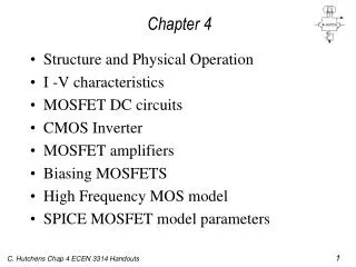
Outline • Motivation: III-V MOSFETs • Approach: Self-aligned source/drain by MBE regrowth • FET and Contacts Results • Conclusion
Why III-V MOSFETs • Silicon MOSFETs: • Scaling limit beyond sub-22 nm Lg • Non-feasibility of sub-0.5 nm equivalent oxide thickness (EOT) Alternative III-V channel materials III-V materials→ lower m*→ higher velocities (veff) Id / Wg = qnsveff Id / Qtransit = veff / Lg
22 nm InGaAs MOSFET Predicted drive current: ~5 mA/mm1,2 Key Challenges • 1 nm EOT gate dielectric • 5 nm channel with back barrier • 15 W-mm source resistance • 5×1019 cm-3 source active doping2 1 Rodwell. IPRM 2008 2 Fischetti. IEDM 2007
InGaAs MOSFET with Source/Drain regrowth Process scalable to 22 nm Source/Drain defined by MBE regrowth Regrowth InGaAs, in situ Mo contact Resistance: 0.5 W-mm2 (2.5 W-mm)* * Wistey, EMC 2008
Process flow Gate definition Sidewall, Source/Drain
Gate Definition: Challenges • Must scale to 22 nm • Dielectric cap surrounding the gate for source/drain regrowth • Metal & Dielectric etch must stop in 5 nm channel • Dry etch must not damage thin channel Process must leave surfaces ready for S/D regrowth
Gate Stack: Multiple Layers & Selective Etches Key: stop etch before reaching dielectric, then gentle low-power etch to stop on dielectric FIB Cross-section Damage free channel SiO2 Cr W Process scalable to sub-100 nm gate lengths
Dielectric etch and sidewall formation Dielectric etch Sidewall definition InGaAs etch
Surface cleaning before regrowth • Clean organics by 30 min UV Ozone • Ex-situ HCl:H2O clean • In-situ 30 min H clean • c(4×2) reconstruction before regrowth • Defect free regrowth InGaAs regrowth InGaAs HAADF-STEM* Interface Epi-ready surface before regrowth, defect free regrowth on processed wafer 2 nm * Wistey, EMC 2008
Height selective Etching* PR Mo PR PR InGaAs Dummy gate No regrowth * Burek, J.Cryst.Growth, submitted for publication
MOSFET characterstics Rs ~ 1 MW-mm! • Extremely low drive current: 2 mA/mm • Extremely high Ron= 10-100 kW • Why is Rs so high?
Source Resistance 1: Poly Growth on InP After regrowth SEM Rough InGaAs regrowth InGaAs regrowth on unprocessed thin InP* • Spotty RHEED during regrowth: faceted growth • InP desorbs P during hydrogen clean or regrowth: InP converts to highly-strained InAs* • From TLM measurement, Rsh= 310 W/□, rc=130 W-mm2 and Rs= 300W-mm Sheet resistance doesn’t explain 1 MΩ-µm source resistance. * Wistey (in preparation)
Source Resistance 2: Gap in Regrowth SEM SEM InGaAs regrowth InGaAs regrowth No regrowth Electron depletion W / Cr / SiO2 gate W / Cr / SiO2 gate No regrowth • No regrowth within 200 nm of gate because of shadowing by gate • Gap region is depleted of electrons • Breakdown at Vg=0V, ~ 8V, consistent with 400 nm gap and InGaAs breakdown field of 20V/mm* High source resistance because of electron depletion in the gap *http://www.ioffe.rssi.ru/SVA/NSM/Semicond/
Regrowth: Solutions High T migration enhanced Epitaxial (MEE) regrowth* smooth InGaAs regrowth on thin InGaP* No Gap gate regrowth interface *Wistey, EMC 2008 Wistey, ICMBE 2008
Conclusion • Scalable III-V MOSFET process with self-aligned source/drain with MBE regrowth • Gate proces and H clean leave a epi-ready 5 nm channel • Low drive current in initial devices because of break in regrowth • Improved regrowth techniques in next generation of devices This work was supported by Semiconductor Research Corporation under the Non-classical CMOS Research Program