Download
1 / 18
200 likes | 852 Views
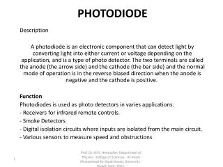
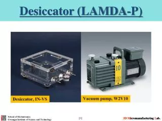
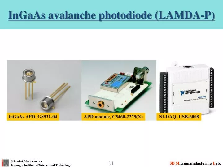
InGaAs avalanche photodiode (LAMDA-P). Introduction of InGaAs APD. The APD (avalanche photodiode) is a high sensitivity photodiode that operates at high speeds and high gain by applying a reverse bias.

E N D
Introduction of InGaAs APD • The APD (avalanche photodiode) is a high sensitivity photodiode that operates at high speeds and high gain by applying a reverse bias. • Delivers a higher S/N than PIN photodiodes and is widely used in optical rangefinders, spatial light transmission, scintillation detectors, etc. • The G8931-04 is an InGaAs APD that delivers a high-speed response of 2.5 Gbps required for trunk line optical fiber communications such as SONET (synchronous optical network), G-PON (gigabit-capable passive optical network) and GE-PON (gigabit ethernet-passive optical network).
Introduction of APD module • This product is a highly sensitive high-speed photo-detector that integrates an avalanche photodiode (hereafter abbreviated APD), a temperature-compensating bias circuit and low noise current-to voltage amplifier circuit. • The temperature-compensating bias circuit has a thermo-sensor that detects the ambient temperature to offset the temperature dependence of the APD gain. It also provides a low ripple bias voltage which is applied to the APD. • The low noise current-to-voltage amplifier circuit uses a low noise operational amplifier, providing a low noise circuit configuration optimized for the APD signal readout. The combination of this amplifier circuit and the low ripple bias circuit enables high-speed light detection with high sensitivity. • In addition, only external DC voltage (±12V) is necessary as power supply, so the module is easy to operate.
Introduction of NI-DAQ • The NI USB-6008 provides low- cost, bus- powered multifunction DAQ functionality for applications such as simple data logging, portable measurements, and academic lab experiments. Use the USB-6008 with the included ready-to-run data logger software to begin taking basic measurements in minutes, or program it using NI LabVIEW or C and the included NI-DAQmx Base measurement services software for a custom measurement system. • 8 analog inputs at 12 or 14 bits, up to 48 kS/s • 2 analog outputs (12-bit, 150 S/s); 12 digital I/O; 32-bit counter • Bus-powered for high mobility; built-in signal connectivity • PC-based Data Acquisition • Each NI USB-6008 requires: Compatible with LabVIEW, LabWindows™/CVI, and Measurement Studio for Visual Studio .NET
APD module operation method • Power Cable and Output Signal Cable Connections. • Power connection: Use the power cable to connect the C5460-2279(X) to the power supply. • Signal cable: Use a coaxial cable for connection to measuring devices such as oscilloscopes. Be sure to terminate the output with 10 kΩto 1MΩ. • Turn the Power On: After the power is turned on, check whether excessive current is flowing the device and whether the device is operating abnormally, for example if smoke is coming out. If any abnormal operation occurs, immediately power off. • After optical adjustment has been made, start measurement.
Connection NI-DAQ with APD • APD module is connected to GND and AI 0 (AI 0+) of NI-DAQ (USB-6008) by using BNC cable to collect the data from APD sensor.
Lab VIEW program for APD module After installing Lab VIEW program, operate “Voltage - Continuous Input(LV12).vi” file.
Lab VIEW program for APD module cont. After operating the program, select the channel of NI-DAQ connected the APD module. The connected channel is “6008/ai0”.
Lab VIEW program for APD module cont. Set the max./min. voltage (±12 V). Power supply should also send ±12 V to APD module.
Lab VIEW program for APD module cont. Before running the program, place to save the measured data should be defined as following steps. Firstly select “Log and Read” and open the folder. Then select the designated folder and write the file name. Finally press “OK” button to save the storage path and run the program.
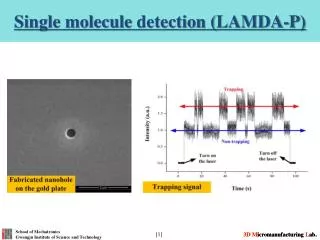
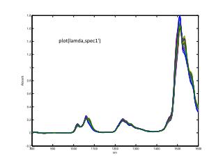
Measurement of the laser signal • If the laser is not emitted, the noise signal is represented as shown in under figure.
Measurement of the laser signal cont. • If the laser is emitted, the voltage signal is increased. The signal is defined by the laser power and scattering.