Download
1 / 1
10 likes | 110 Views
Revision with Reason. Revision with Reason. Revision with Reason. No. No. No. Date. Date. Date. Initials. Initials. Initials. Profile view. 1/16 in. 5 in. Project Unbreakable Debra Rich & Carmen Prieto • ME 104Q • Fall 2004. Abstract. Results.

E N D
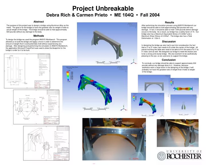
Revision with Reason Revision with Reason Revision with Reason No. No. No. Date Date Date Initials Initials Initials Profile view 1/16 in 5 in. Project Unbreakable Debra Rich & Carmen Prieto • ME 104Q • Fall 2004 Abstract Results The purpose of this project was to design a bridge using Aluminum Alloy as the metal. The goal is for the bridge to have the greatest ratio for weight it holds to actual weight of the bridge. The bridge should be able to hold approximately 500 pounds without any damage to the body. After performing the simulation process using ANSYS Workbench our bridge should be able to hold approximating 500 pounds with any damage. In fact, it should be able to hold 7,000 pounds before damage occurs to the body. As a result, our bridge has a safety factor of 15. Our bridge also has a Maximum Equivalent Stress of 3.539e7 and a Maximum Shear Stress of 2.035e7. The bridge also has a Total Deformation of .132e-3. Methods To design the bridge we used the program ANSYS Workbench. This program allowed us to build the bridge and apply a force in order to determine the amount of weight that it could potentially hold without experiencing any damage. After designing and performing the simulation in ANSYS Workbench, the application Microsoft PowerPoint was used to draw the blueprints for the bridge in order for it to be built. Discussion In designing the bridge we also had to put into consideration the fact that a 3” by 5” index card needs to fit under the center of the bridge. All pieces touching the table also need to be able to fit in the area of a 3” by 5” index card as well. We designed our bridge to meet this factors and to be a strong and sturdy bridge. We also wanted it to be aesthetically pleasing to the eye, so we used arcs to support the bridge. .50 0.50 Conclusion NOTES: Material 6061-T651 sheet Aluminum Shear to Size Break Sharp edges Drill Holes when flat (4 places) relative to exterior corners and the middle. Fold 90 degrees in two places along dotted fold lines to form part as shown in Drawing #A-004. Both Bent Legs should be same length. After bend the gap span should be 1 inch exactly. All dimensions in inch units. Unless otherwise indicated, use default tolerances below x.x +/- 0.050” x.xx +/- 0.010” x.xxx +/- 0.005” Angles +/- 2o To conclude, our bridge should be able to support approximately 500 pounds without any damage done to it. However, because aesthetics were a large factor in the designing of the bridge, it will probably not have the greatest ratio of weight that it holds to weight of the bridge. 11.50 5.50 Drawing No. ME104Q-Project 1.125 1.125 1.125 Descriptive Part Name Quantity Required Bridge Deck 0.063 1 3.25 Drawing Type Drawing Size Scale as Drawn Scale as Printed Detail A 8 x10 1:1 =100% 1:1, 1indrawing=1inpart Designed by Checked by Engineer D. Rich & C. Prieto D. Quesnel Date of This Revision Engineer Phone # Drawing Issue Date 12/08/04 12/08/04 275-5215 Front view NOTES: Material 6061-T651 sheet Aluminum Aloy Shear to Size Break Sharp edges Drill Holes when flat (6 places) relative to exterior corners. Fold 90 degrees upwards as if the sheet where laid on the table in the two places along dotted fold lines to form part as shown in Drawing #A-004. Both Bent Legs should be same length. The proceeding page shows holes for rivets to got through. All dimensions in inch units. Unless otherwise indicated, use default tolerances below x.x +/- 0.050” x.xx +/- 0.010” x.xxx +/- 0.005” Angles +/- 2o 11.5 in. 3.5 in. 1 in. 1 in. 1.5 in. 1.5 in. 2.5 2.5 5 in. 3 in. 3.5 in. 3.5 in. 1.5 in. 1 in. 1 in. 1.5 in. 1 in. 1 in. 9.5 in. 1.5 in. 1.5 in. Drawing No. ME104Q-Project Fold on these two dotted lines Descriptive Part Name Quantity Required Bridge leg 2 Drawing Type Drawing Size Scale as Drawn Scale as Printed detail A 8 x10 1:1 =100% 1:1, 1indrawing=1inpart Designed by Checked by Engineer Carm and Debb D. Quesnel Drawing Issue Date Date of This Revision Engineer Phone # 12/08/04 12/08/04 Xxx-yyyy NOTES: Material 6061-T651 sheet Aluminum Aloy Shear to Size Break Sharp edges Drill Holes when flat (12 places) relative to exterior corners. Circles represent rivets to be placed. Place A-002 exactly 3.25 from the ends of the bridge deck and Rivets that appear on the presentable surface of this bridge should be reflected onto the other bridge leg. All dimensions in inch units. Unless otherwise indicated, use default tolerances below x.x +/- 0.050” x.xx +/- 0.010” x.xxx +/- 0.005” Angles +/- 2o .875 1 1.125 .875 1 in. 1.0625 Bill of Materials A-001 1 1 Bridge Deck Bridge Leg 2 2 A-002 .75 Bridge deck Support 3 2 A-003 Aluminum Pop Rivets 1/8” f 4 12 Any supplier Item Quantity Supplier Drawing No. ME104Q-Project Descriptive Part Name Quantity Required Bridge assembly 1 Drawing Type Drawing Size Scale as Drawn Scale as Printed detail A 8 x10 1:1 =100% 1:1, 1indrawing=1inpart Designed by Checked by Engineer Carm and Debb D. Quesnel Drawing Issue Date Date of This Revision Engineer Phone # 12/08/04 Xxx-yyyy 12/08/04