Download
1 / 27
590 likes | 1.15k Views
Characterization of conduction mechanism of dielectric thin film and its relation with interface characteristics. Introduction. Electrical quality of gate dielectric. Dielectric constant. Leakage current. V T stability. Ion density. Poole- Frenkel. Charge trapping. Ion’s TEC.

E N D
Characterization of conduction mechanism of dielectric thin film and its relation with interface characteristics
Introduction Electrical quality of gate dielectric Dielectric constant Leakage current VT stability Ion density Poole-Frenkel Charge trapping Ion’s TEC Space charge limited Charge detrapping Frequency of POM Fowler Nordheim Interface dipole Trap-assisted tunneling Schottky emission Direct tunneling
Conduction mechanisms Bulk-limited process Poole-Frenkel Thermal electron excitation from localized state to conduction band (Hopping through traps) Barrier reduction by E-field Thermal fluctuation
Conduction mechanisms Bulk-limited process Space charge limited 3 formation processes : Space charge in solid dielectric Dipole orientation Ion migration Charge transfer
Conduction mechanisms Interface-limited process Schottky emission 1) Electric field lowers surface barrier 2) Thermal energy given to the carrier overcomes the barrier
Conduction mechanisms Interface-limited process Fowler-Nordheim Trap-assisted tunneling Direct tunneling Tunneling into: Tunneling through: Dielectric CB Dielectric trap state Dielectric bandgap
Conduction mechanisms Temperature dependency Temperature dependent Poole-Frenkel hopping Schottky emission Temperature independent Tunneling : dependent to barrier height, width
Conduction mechanisms I-V relationship Poole-frenkel: J ~ Vexp(V1/2) Schottky emission: J ~ exp(V1/2) Annealing@500ºC Reduction of trap site
Conduction mechanisms I-V relationship After annealing, Trap-independent current is rather significant 2) Fowler-Nordheimat high voltage (Tunneling process generally require higher Electric field) 1) Schottkyemission at low voltage
Conduction mechanisms Tunneling currents 3 tunneling mechanisms are not very distinguishable No difference in J-V characteristic & No temperature dependency Nordheim? Trap-assisted? Direct? Tunneling has thickness dependency Trap assisted tunneling at thicker film
Interface defect state Interface & tunneling Interface trap enhances tunneling conduction Increased current density: Interface trap density
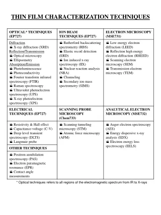
Interface trap reduction X-ray diffraction Post treatment of PECVD-HfO2 (Combination of thermal anneling & N2, NH3 plasma) Crystallization at 600ºC (without plasma treatment) Crystallization at 800ºC (plasma-treated)
Interface trap reduction AES depth profile N2 plasma ~8 at.% N at the HfO2/Si interface NH3 plasma ~8.3 at.% N at the HfO2/Si interface Nitrogen incorporation influence crystallization temperature (Nitrogen was uniformly diffused after 700ºC annealing)
Interface trap reduction Leakage current density Plasma treatment effectively improved current density Bottomside treatment was more effective Untreated Topside Bottomside treatment Topside treatment Bottomside Plasma Plasma HfO2 Si Si
Interface trap reduction Trap states in HfO2 Negatively charged vacancy: Formed by distortion of Hafnium ions O Vacancy Interstitial: Simple I2- is at the valence band
Interface trap reduction Nitrogen effect Model A Most stable Trap site is eliminated Defects are not passivated but,
Interface trap reduction Nitrogen effect Decrease in attractive Coulomb interaction from Hf4+ ions around VO N-induced atomistic relaxation Drastic VO level elevation Removal of leakage paths Electron transfer from V0 to N Outward movement of Hf4+
Interface trap reduction Fluorine implantation Leakage current is effectively decreased by F implantation High Si-F bond strength: Replacing Si-H, Si dangling bonds Increase interface trap formation energy
Interface trap reduction Gate deposition effect High leakage current with CVD-Si gate Reducing ambient → Oxygen vacancy formation → Increased trap density Leakage current is drastically decreased when PVD-gate is deposited on
Conclusion • Interface-limited conduction is important in thin high-k dielectric • Interface trap enhances tunneling current • Generally O deficiency is the cause of charge trap • Characterization of interface trap is important • Interface trap can be reduced by post-treatment like N2 plasma
Future work • Near future • Surface sol-gel active layer • Microwave annealing (reproducibility) • Material characterization • Future • Establishment of interface trap characterization technique • Determination effect of processes on dielectric interface • Applying trap-reduction technics
Experiment Gate isolation Result: still have large leakage current - Chemical damage into SiO2 layer (during patterned BOE etching) Experiment for confirmation Current through thermal SiO2 SiO2 GIO SiO2 HfO2 Si
Future work Device fabrication Pattered ITO electrode Perfectly isolated gate Surface roughness Precursor solution filtering Cleaner drying environment Surface sol-gel active layer TiO2, SnO2, TixSn1-xO2 ITO Glass
Experiment Device TTFT with ITO gate ITO Glass
Experiment Patterned ITO Conductive - No damage from HCl patterning Source-drain (no gate contact) No punch-through
Experiment Leakage test Breakdown - ~ 6.5V Device failure by leakage current
Experiment Microwave annealing Leakage current is decreased in microwave-annealed sample