Download
1 / 24
270 likes | 297 Views
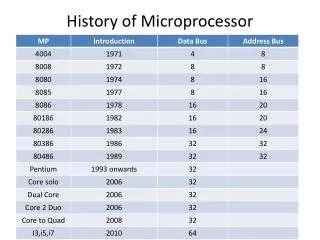
Introduction of microprocessor. Chapter outline. Block diagram of a computer system Basic components of a computer system using block diagrams: Cpu Memory Input and output unit Evolution of microprocessor : 4,8,16,32 dan 64 byte Nibble, byte, word dan longword

E N D
Chapter outline • Block diagram of a computer system • Basic components of a computer system using block diagrams: • Cpu • Memory • Input and output unit • Evolution of microprocessor : 4,8,16,32 dan 64 byte • Nibble, byte, word dan longword • Fecthing and execution cycles. • Internal structure and basic operation of a microprocessor (arithmetic and logic unit, control unit, register sets, accumulator, condition code register, program counter, stack pointer) • Bus system: data bus, address bus and control bus. • Microprocessor clock system • Examples of microprocessor: 8085,8086.
DIAGRAM OF A COMPUTER SYSTEM A computer is a programmable machine that receives input, stores and manipulates data//information, and provides output in a useful format. Diagram Of A Computer System
BLOCK DIAGRAM OF A BASIC COMPUTER SYSTEM Basic computer system consist of a Central processing unit (CPU), memory (RAM and ROM), input/output (I/O) unit. Address bus CPU ROM RAM I/O interface I/O devices Data bus Control bus Block diagram of a basic computer system
Basic component of microcomputer • CPU - Central Processing Unit • the portion of a computer system that carries out the instructions of a computer program • the primary element carrying out the computer's functions. It is the unit that reads and executes program instructions. • The data in the instruction tells the processor what to do. Pentium D dual core processors
2. Memory • physical devices used to store data or programs. • Computer main memory comes in two principal varieties: random-access memory (RAM) and read-only memory (ROM). • RAM can be read and written to anytime the CPU commands it, but ROM is pre-loaded with data and software that never changes, so the CPU can only read from it. • ROM is typically used to store the computer's initial start-up instructions. • In general, the contents of RAM are erased when the power to the computer is turned off, but ROM retains its data indefinitely. • In a PC, the ROM contains a specialized program called the BIOS that orchestrates loading the computer's operating system from the hard disk drive into RAM whenever the computer is turned on or reset.
3. I/O Unit • Input/output (I/O), refers to the communication between an information processing system (such as a computer), and the outside world possibly a human, or another information processing system. • Inputs are the signals or data received by the system, and outputs are the signals or data sent from it • Devices that provide input or output to the computer are called peripherals • On a typical personal computer, peripherals include input devices like the keyboard and mouse, and output devices such as the display and printer. Hard disk drives, floppy disk drives and optical disc drives serve as both input and output devices. Computer networking is another form of I/O.
ALU Register Section Address bus Data bus Control and timing section Control bus Internal structure and basic operation of microprocessor Block diagram of a microprocessor
Arithmetic and logic unit (ALU) • The component that performs the arithmetic and logical operations • the most important components in a microprocessor, and is typically the part of the processor that is designed first. • able to perform the basic logical operations (AND, OR), including the addition operation.
Internal structure of ALU 2 bits of ALU 4 bits of ALU
Control unit • The circuitry that controls the flow of information through the processor, and coordinates the activities of the other units within it. • In a way, it is the "brain within the brain", as it controls what happens inside the processor, which in turn controls the rest of the PC. • On a regular processor, the control unit performs the tasks of fetching, decoding, managing execution and then storing results.
Register sets • The register section/array consists completely of circuitry used to temporarily store data or program codes until they are sent to the ALU or to the control section or to memory. • The number of registers are different for any particular CPU and the more register a CPU have will result in easier programming tasks. • Registers are normally measured by the number of bits they can hold, for example, an "8-bit register" or a "32-bit register".
31 16 15 8 7 0 D0 D1 D2 DATA REGISTERS D3 D4 D5 D6 D7 31 16 15 8 7 0 A0 A1 A2 ADDRESS REGISTERS A3 A4 A5 A6 A7 USER STACK POINTER STACK POINTER A7 SUPERVISOR STACK POINTER PC PROGRAM CONTER 15 8 7 0 SR STATUS REGISTER SYSTEM BYTE USER VYTE Register in motorola 68000 microprocessor
accumulator • a register in which intermediate arithmetic and logic results are stored. • example for accumulator use is summing a list of numbers. • The accumulator is initially set to zero, then each number in turn is added to the value in the accumulator. • Only when all numbers have been added is the result held in the accumulator written to main memory or to another, non-accumulator, CPU register.
Condition code register (CCR) = Flags • an 8 bit register used to store the status of CPU, such as carry, zero, overflow and half carry.
Program counter (PC) • a 16 bit register, used to store the next address of the operation code to be fetched by the CPU. • Not much use in programming, but as an indicator to user only. • Purpose of PC in a Microprocessor • to store address of tos (top of stack) • to store address of next instruction to be executed. • count the number of instructions.
Stack pointer (SP) • The stack is configured as a data structure that grows downward from high memory to low memory. • At any given time, the SP holds the 16-bit address of the next free location in the stack. • The stack acts like any other stack when there is a subroutine call or on an interrupt. ie. pushing the return address on a jump, and retrieving it after the operation is complete to come back to its original location.
Data bus • The data bus is 'bi-directional' • data or instruction codes from memory or input/output.are transferred into the microprocessor • the result of an operation or computation is sent out from the microprocessor to the memory or input/output. • Depending on the particular microprocessor, the data bus can handle 8 bit or 16 bit data.
Address bus • The address bus is 'unidirectional', over which the microprocessor sends an address code to the memory or input/output. • The size (width) of the address bus is specified by the number of bits it can handle. • The more bits there are in the address bus, the more memory locations a microprocessor can access. • A 16 bit address bus is capable of addressing 65,536 (64K) addresses.
Control bus • The control bus is used by the microprocessor to send out or receive timing and control signals in order to coordinate and regulate its operation and to communicate with other devices, i.e. memory or input/output.
Micro processor clock • Also called clock rate, the speed at which a microprocessor executes instructions. Every computer contains an internal clock that regulates the rate at which instructions are executed and synchronizes all the various computer components.
Examples of micro processor • Intel 8086 • Motorola 6800 • Zilog Z80