Download
1 / 43
430 likes | 555 Views
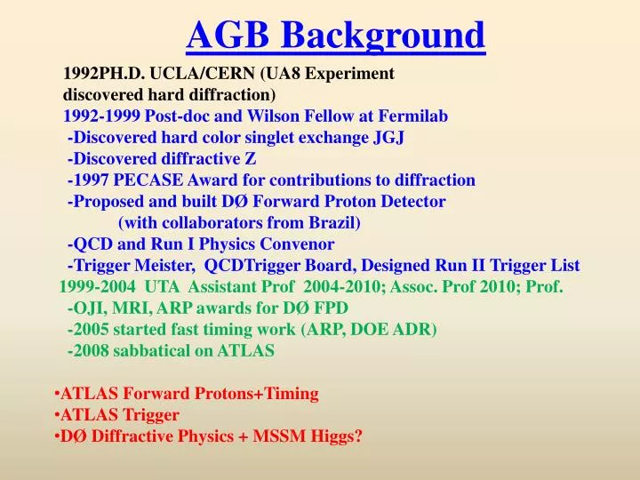
AGB Background. 1992PH.D. UCLA/CERN (UA8 Experiment discovered hard diffraction) 1992-1999 Post-doc and Wilson Fellow at Fermilab -Discovered hard color singlet exchange JGJ -Discovered diffractive Z -1997 PECASE Award for contributions to diffraction

E N D
AGB Background • 1992PH.D. UCLA/CERN (UA8 Experiment • discovered hard diffraction) • 1992-1999 Post-doc and Wilson Fellow at Fermilab • -Discovered hard color singlet exchange JGJ • -Discovered diffractive Z • -1997 PECASE Award for contributions to diffraction • -Proposed and built DØ Forward Proton Detector • (with collaborators from Brazil) • -QCD and Run I Physics Convenor • -Trigger Meister, QCDTrigger Board, Designed Run II Trigger List • 1999-2004 UTA Assistant Prof 2004-2010; Assoc. Prof 2010; Prof. • -OJI, MRI, ARP awards for DØ FPD • -2005 started fast timing work (ARP, DOE ADR) • -2008 sabbatical on ATLAS • ATLAS Forward Protons+Timing • ATLAS Trigger • DØ Diffractive Physics + MSSM Higgs?
ATLAS Forward Proton Upgrade Andrew Brandt, University of Texas, Arlington AFP concept: adds new ATLAS sub-detectors at 220 and 420 m upstream and downstream of central detector to precisely measure the scattered protons to complement ATLAS discovery program. These detectors are designed to run at a luminosity of 1034 cm-2s-1 and operate with standard optics (need high luminosity for discovery physics) H 220 m 420 m beam LHC magnets p’ p’ • AFP Components • Rad-hard edgeless 3D silicon detectors with resolution ~10 m, 1rad • Timing detectors to reject overlap background (SD+JJ+SD) • 3) New Connection Cryostat at 420m • 4) “Hamburg Beam Pipe” instead of Roman Pots AFP Detector
AFP Evolution • 2000 Khoze, Martin, Ryskin (KMR): Exclusive Higgs prediction Eur.Phys.J.C14:525-534,2000, hep-ph/0002072 • 2003-2004 Joint CMS/ATLAS FP420 R&D collaboration forms • 2005 FP420 LOI presented to LHCC CERN-LHCC-2005-0254 “LHCC acknowledges the scientific merit of the FP420 physics programme and the interest in exploring its feasibility” • 2006-7 Some R&D funding, major technical progress, RP220 formed • 2008 AFP formed, cryostat design finished, LOI submitted to ATLAS • 2009 “AFP year in review”, FP420 R&D document published “The FP420 R&D Project: Higgs and New Physics with Forward Protons at the LHC,” FP420 Collaboration, arXiv:0806.0302v2, published in J. Inst.: 2009_JINST_4_T10001, http://www.iop.org/EJ/abstract/1748-0221/4/10/T10001. • 2010 AFP LOI approved, physics case acknowledged, encouraged to prepare Technical Proposal for 2011, UK funding cancelled, adopt staged approach: 220 m in 2013, 420 m in 2016
What does AFP Provide? Acceptance >40% for wide range of resonance mass • Mass and rapidity of central system, assuming central exclusive production (CEP) process, where momentum lost by protons goes into central system • Mass resolution • of 3-5 GeVper event Combination of 220 and 420 is key to physics reach! 420- 420 420- 220 220- 220 Allows ATLAS to use LHC as a tunable s glu-glu or collider while simultaneously pursuing standard ATLAS physics program
How does CEP work? Typical Higgs Production “+” “=” CEP Higgs pp gg H +x pp p+H+p • Extra “screening ” gluon conserves color, keeps proton intact (and reduces your ) • CEP defined as ppp+X+p , where protons are scattered at small angles, but remain intact, with all of their lost energy going towards production of the system X • Central system produced in Jz=0++ (C-even, P-even) state, this results in di-quark production being suppressed • Process observed by CDF: exclusive dijetsPR D77, 052004 (2008) and exclusive χcPRL 102, 242001 (2009) Find a CEP resonance (for ex. Higgs) and you have measured its quantum numbers (0++ )!!
MSSM and CEP • Models with extended Higgs sectors, such as the MSSM, typically produce a light Higgs (h) with SM-like properties and a heavy Higgs (H) which decouples from Gauge boson. This implies: • no HVV coupling (V=W, Z) • no weak boson fusion • no HZZ • big enhancement in • pseudoscalar A does not • couple to CEP R=(MSSMH)/(SMH) H→bb, mhmax, μ = 200 GeV R=300 mA (GeV) For the MSSM and related models, AFP is likely to provide the only way to determine the Higgs quantum #’s and the coupling to b-quarks, and will provide an excellent mass measurement
AFP Studies • AFP manpower primarily dedicated to detector R&D and technical studies, however… • We (Brandt, Pal, et al.) performed studied over last few years to validate the • theory predictions , using 120 GeV for and 160 GeV for • We validated the exclusivity cuts needed to reduce the overlap background, including • tracking rejection with full detector simulation • In the bb channel Standard Model Higgs without forward protons is believed • to be impossible. With FP’s it is really, really hard. We obtain a signal to background • including a believable trigger (using Phase I calo upgrade and 220 m proton tag) of • near 1 up to 2x1033, but with only about 1 signal event/ 30 fb-1 after cuts to control • the overlap background . With the x8 MSSM enhancement factor, we get comparable • significance as JHEP 0710:090,2 007 • We produced a luminosity model that showed that we can obtain comparable • significance/fb-1 for a store starting at 1x1034 as we could with continuous 5x1033 • So 120 GeV , requires a 5-10 “MSSM factor” for 4 observation in 100 fb-1 • For we showed that the backgrounds are easily controlled at • 160 GeV, and this looks like a promising channel (4 observation in 100 fb-1 ) • down to ~130 GeV or so [Note smaller bkgd, easier trigger >1034 operation]
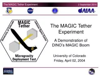
Forward Proton Fast Timing WHY? Pileup Background Rejection Ex: Two protons from one interaction and two b-jets from another Use time difference between protons to measure z-vertex and compare with tracking z-vertex measured with silicon detector How? How Fast? 10 picoseconds is design goal (light travels 3mm in 10 psec!) gives large factor of background rejection; Stage I: 2013 220 m lum up to several 1033 t < 20 ps Stage II: 2016 add 420 m 1034 t < 10 ps (<4 years)
Timing System Requirements • 10 ps or better resolution • Acceptance over full range of proton x+y • Near 100% efficiency • High rate capability • Segmented : for multi-proton timing and L1 trigger • Robust: capable of operating with little or no intervention in radiation environment (tunnel) - PMT’s, detectors, cables, and electronics must be able to tolerate radiation levels (for PMT’s this includes tolerance to external radiation damage, as well as to internal photocathode damage) - Backgrounds from other particles must not impair operation Andrew Brandt (UTA) AFP Workshop Prague
QUARTIC is Primary AFP Timing Detector proton UTA, Alberta, Giessen, Stonybrook (w/help from Louvain and FNAL) photons 4x8 array of 5x5 mm2 fused silica bars Only need a 40 ps measurement if you can do it 16 times: 2 detectors with 8 bars each, with about 10 pe’s per bar MCP-PMT • Multiple measurements with “modest” resolution simplifies requirements in all phases of system • 1) We have a readout solution for this option • We can have a several meter cable run to a lower radiation area where electronics will be located • Segmentation is natural for this detector • Possible optimization with quartz fibers instead of bars
Micro-Channel Plate Photomultiplier Tube Burle/Photonis 64 channel 10 and 25 m pore MCP-PMTs have been tested extensively with test beam and laser and would be default for first stage except for lifetime issues
MCP-PMT Requirements Excellent time resolution: 20-30 ps or better for 10 pe’s High rate capability: Imax ~ 3 A/cm2 Long Lifetime: Q~ 30 C/cm2/year at 400 nm Multi anode: pixel size of ~6 mm x 6mm Pore Size: 10 m or better Tube Size: 40 mm round, 1 or 2 inch square Need to have capability of measurements in different parts of tube between 0-2 ns apart, and in same part of the tube 25 ns apart Photek 240 (1ch) Hamamatsu SL10 (4x4)
QUARTIC Timing 2008 CERN TB Dt Npe=(area/rms)2 56.6/1.4=40 ps/bar using Burle 64 channel 10 m pore tube including CFD! Time difference between two 9 cm quartz bars after CFD implies a single bar resolution of 40 ps for about 10 pe’s (10 pe’s from simulations/Test Beam).
QUARTIC Efficiency CERN TB (a) (b) All tracks (Bonn Silicon Telescope) Tracks with a Quartz bar on Events Shape due to veto counter with 15mm diameter hole 6mm Use tracking (b)/(a) to determine that QUARTIC bar efficiency is high and uniform (c) Efficiency 6 mm Strip #
Established with DOE ADR, Texas ARP funds, some supplemental support for UG’s - Ian Howley (Ph. D. student), Ryan Hall (was UG, now in UTA Ph. D. program), both students moving on soon… - Monica Hew, Keith Gray, James Bourbeau (UG)+… beam splitter mirror LeCroy Wavemaster 6 GHz Oscilloscope filter MCP-PMT lenses laser Hamamatsu PLP-10 Laser Power Supply Laser Box Andrew Brandt UTA
(a) UTA Laser System Beam Mode Fiber Mode (c) (b) (d)
Timing vs. Number of PE’s 10 m Planacon If then timing independent of HV/gain
10 pe Time Resolution from Laser Tests Laser tests of Photonis 10 µm tube show that with sufficient amplification there is no dependence of timing on gain (low gain operation extends lifetime of tube)
Saturation from Laser Tests Saturation refers to the reduction in amplitude of the output signal due to the pores becoming busy at the rate increases (typically 1 msec recovery time/pore). This plot shows that saturation is a local phenomena, and is unaffected by multiple channels being on at the same time. No rate dependence on number of pixels hit (that’s a good thing!) Andrew Brandt UTA
Current/area for 10 m Tube Last point is 2.0 μA/cm2 ~meeting the high luminosity goal. Photonis has made Planacon with 10x higher current capability which exceed meet our rate requirements (Note: even with saturation we still obtain the same time resolution!!!) Andrew Brandt UTA
Beam vs Fiber Fiber timing not as good, but allows us flexibility for some characterization tests
SQRT(N)? From averaging time of four measurements on event-by-event basis If single fiber gives 35 ps then 4 fibers should give 17 ps; but note that with many fibers plugged in, individual pixel gets light leaking from neighboring channel, need to test that this effect is reproduced in test beam
Cross Talk Photons • Initial PE’s “bouncing” into nearby channels, or cascade electrons hitting a neighboring anode • Results in a false signal in the adjacent channel, which may distort measurements of the real time value Optical Crosstalk Photoelectron Rebound Electrical Crosstalk Anode 1 Anode 2
Protons in Adjacent Pixels The amount of light sharing affects ability to measure two adjacent rows/columns independently As one proton enters some time before the other, the second timing measurement shifts due to cross talk Top View
Cross Talk Results • Tested a prototype BurlePlanacon tube using variable length fibers • Examined both row and column effect of spillover light 100, 250 and 500 ps before the target pulse • About10% of the pulse is detected in adjacent, empty pixels • Data shows that early light is not significantly affected by late light • Late light mean time is shifted, but is not totally dominated by the early pulse • Late time measurement degrades significantly as Δt increases • Exploring ways to reduce this effect
Electronics Layout t~5ps Stony Brook t~25ps t~5ps t~15ps ZX60 4 GHz amplifier CFD Louvain, Alberta HPTDC Alberta
Reference Timing Reference timing is needed to connect two arms ~1km apart; what we want is TL-TR, what we measure is (TL-Tref)-(TR-Tref), so need small jitter in Tref This setup has just been tested at SLAC to give <10 ps with 1000 ft cable The reference system uses a phase lock loop to maintain a constant number of wavelengths in a 100m cable. This synchronizes the phase of the RF at each end of the cable. A voltage controlled oscillator (VCO) launches a signal down the cable where it is reflected and sent back. The returned signal is then interfered with an external RF reference to synchronize it with the reference. At the end of the 100m cable the signal is sampled with a directional coupler which mixes the signal to produce a DC level. That DC level is fed back to the VCO to maintain a constant number of wavelengths in the cable. Andrew Brandt (UTA) AFP Workshop Prague
Lifetime Issues Lifetime due to positive ions damaging the photocathode is believed to be proportional to extracted charge: Q/year = I*107 sec/year Q for 3 A/cm2 is 30 C/cm2/yr Can reduce this requirement with fiber detector but still off by at least a factor of 20, so developed an R&D plan to pursue this Andrew Brandt (UTA) AFP Workshop Prague
Options for Improved Lifetime MCP-PMT Pursuing funds to develop and test longer lifetime tubes. Photek will build tubes to our specification (no funding for this yet!). Photonis will insert Arradiance modified MCPs into their tubes (just received notification of NSF SBIR funding with Arradiance) Ion barrier, already demonstrated, this promises a factor 5 to 6 lifetime improvement (Hamamatsu SL10 may be better than this) Electron scrubbing demonstrated by Photonis gives a factor of ~5 lifetime improvement Z-stack promises a factor of 10 lifetime improvement (A.Yu. Barnyakov, et al., Nucl. Instr. and Meth. A 598 (2009) 160) Arradiance coated MCP’s, to be demonstrated, this promises a factor of 10 or more lifetime improvement Various combinations of these factors are possible and should give multiplicative improvement factors, except for the electron scrubbing and Arradiance coating, which would be expected to be orthogonal Andrew Brandt (UTA) AFP Workshop Prague
MCP-PMT Alterntive: SIPM Ronzhin, Albrow At FNAL have been studying
SIPM (4 pe average) 16 ps for 25 pe (expected amount of Light using quartz radiator in front of SiPM)
CERN/FNAL Test Beam Analysis of CERN Aug 23-30 TB in progress, some of tests to be repeated at FNAL Nov. 16-21 with UTA students, better trigger,amplifier shielding and protection QUARTIC: • New quartz bar prototype test (Alberta 8 long-bar prototype), use scope to measure raw signal and compare to laser, pulse height, number of pe’s, timing resolution • 8 channel electronics test AMP->CFD->HPTDC • [sqrt(N) test] study coherent noise effects and 8-channel timing • compare 25 um and 10 um Burle tubes (single channel and also 8 channel) • Color dispersion tests with long bar and filter FIBER: • Giessen fiber detector with Giessen readout • Alberta fiber bundle comparison tests SiPM Tests Andrew Brandt UTA Test Beam Planning
2011 UTA Laser Plan • Goals: - Finish cross talk and multi-proton studies - Submit results of these and other laser studies over the past 1.5 years to J. Inst (this also includes detailed studies of timing of Burle 10 and 25 m tubes, saturation, rates, Photek tube, etc. ) - Lifetime and characterization of Arradiance/Photonis tubes from SBIR - Buy/Borrow Hamamatsu SL10? Photek tube(s) Andrew Brandt UTA
Timing Conclusions • We have developed a fast timing system for AFP that seems to be capable of ~10 ps resolution, still some loose ends to address • Work in progress: • 1) final optimization of detector (quartz fibers could lower maximum rate by 2-3 by more sensible binning) • 2) developing final HPTDC board (Alberta) and trigger circuit (Stony Brook) • 3) test beam and laser tests • 4) developing and testing long-life MCP-PMT (new funding) • 5) evaluating radiation tolerance of all components and upgrading as needed • 6) SiPm alternative • Writing up results for Technical Proposal
UTA Role in AFP • Brandt: • has been co-leader/deputy leader of AFP since its inception • was primary editor of LOI, major editor of FP420 doc • leads the fast timing effort for AFP • with Pal studied/strengthened the physics case • developed L1 trigger detector • prepared PMT lifetime note, L1 trigger detector/latency • note, co-edited response to referee questions • prepared Barcelona talk key to LOI acceptance • worked with Steve Watts and now Christophe Royon • on approval/funding strategy • Co-author and editor of Technical Proposal AFP Andrew Brandt UTA DOE Review
AFP Status • LOI approved, Technical Proposal being prepared • UK groups funding cut leaves a big hole • ATLAS Management has been encouraging, is developing a plan with us for Stage I installation in 2012/2013, including TP approval in 2011, TDR/LHCC approval in 2012 • R&D funds still needed • HPS at CMS has similar plans will be added officially to CMS Upgrade in December (just received US CMS Upgrade funding)!
Fourier Transform of Signal Lecroy 8620A Wavemaster 6 GHz 20 Gs/s 10 m planacon, 40 pe’s -whole signal is in first GHz: rule of thumb BW=1/3*risetime=1/3*400ps=0.8 GHz -scope bandwidth is 6 GHz -cell phone/wireless noise contributions visible -we use high bandwidth amp because of low noise and then add filtering. A 1 GHz low noise amplifier would likely be preferable, but we couldn’t find one so we filter (1.5 GHz filter helps a little, 1 GHz starts to cut into signal degrade performance) 1 GHz Andrew Brandt Clermont-Ferrand
Photek 210 with 8 GHz amp 10 pe’s Some signal out to 3-4 GHz 1 GHz 8.7 ps with CFD vs 11.6 ps for raw pulse (compared to 23 ps for Burle tube) 80 ps rise time