Download
1 / 27
330 likes | 639 Views
Data Link Control Protocols. Data link control protocol Provides a layer of control between systems on a transmission medium referred to as data link . DLC protocol objectives: Frame synchronization Flow Control Error Control Addressing Distinction between control and data information

E N D
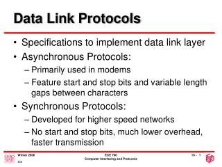
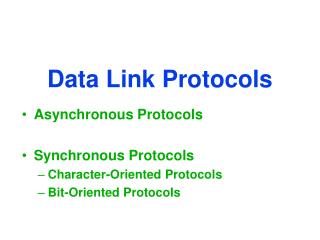
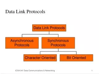
Data Link Control Protocols • Data link control protocol • Provides a layer of control between systems on a transmission medium referred to as data link. • DLC protocol objectives: • Frame synchronization • Flow Control • Error Control • Addressing • Distinction between control and data information • Link management • Initiation, maintenance and termination • High-level Data Link Control Protocol.
Ensuring the sending entity does not overwhelm the receiving entity Receiver must control the flow of incoming data to its buffer. Restrict incoming data to prevent its overflow of its resources (buffers) Transmission time Time taken to emit all bits of the frame into medium Proportional to the length of the frame Propagation time Time for a bit to traverse the link Flow Control
Source transmits frame Destination receives frame and replies with acknowledgement Source waits for ACK before sending next frame Destination can stop flow by not send ACK Works well for a few large frames Large block of data may be split into small frames (fragmentation) Limited buffer size Errors detected sooner (when whole frame received) On error, retransmission of smaller frames is needed Prevents one station occupying medium for long periods Stop and wait becomes inadequate Stop and Wait
Stop and Wait Link Utilization • R = data rate of the link in bps • d= length (distance) of the link in meters • V = velocity of propagation in m/s • B = length of the link in bits • (bits present when a stream fully occupies the link) • a = propagation time/ transmission time • a = B/L
Sliding Windows Flow Control • Allow multiple frames to be in transit • Receiver has buffer W long • Transmitter can send up to W frames without ACK • Each frame is numbered • ACK includes number of next frame expected • Sequence number bounded by size of field (k) • Frames are numbered modulo 2k
Sliding Window Enhancements • Receiver can acknowledge frames without permitting further transmission (Receive Not Ready) • Must send a normal acknowledge to resume • If duplex, use piggybacking • If no data to send, use acknowledgement frame • If data but no acknowledgement to send, send last acknowledgement number again, or have ACK valid flag (TCP) • Sliding window is a form of pipelining.
Detection and correction of errors Lost frames Damaged frames Automatic repeat request Error detection Positive acknowledgment Retransmission after timeout Negative acknowledgement and retransmission Automatic Request ARQ Stop and wait Go back N Selective reject (selective retransmission) Error Control
Stop and Wait • Source transmits single frame • Wait for ACK • If received frame damaged, discard it • Transmitter has timeout • If no ACK within timeout, retransmit • If ACK damaged,transmitter will not recognize it • Transmitter will retransmit • Receive gets two copies of frame • Use ACK0 and ACK1 • Pros • Simple • Cons • Inefficient
Go Back N (1) • Based on sliding window • If no error, ACK as usual with next frame expected • Use window to control number of outstanding frames • If error, reply with rejection • Discard that frame and all future frames until error frame received correctly • Transmitter must go back and retransmit that frame and all subsequent frames
Go Back N - Damaged Frame • Receiver detects error in frame i • Receiver sends rejection-i • Transmitter gets rejection-i • Transmitter retransmits frame i and all subsequent
Lost Frame (case 1) Frame i lost Transmitter sends i+1 Receiver gets frame i+1 out of sequence Receiver send reject i Transmitter goes back to frame i and retransmits Lost Frame (case 2) Frame i lost and no additional frame sent Receiver gets nothing and returns neither acknowledgement nor rejection Transmitter times out and sends acknowledgement frame with P bit set to 1 Receiver interprets this as command which it acknowledges with the number of the next frame it expects (frame i ) Transmitter then retransmits frame i Go Back N - Lost Frame
Go Back N - Damaged Acknowledgement • Receiver gets frame i and send acknowledgement (i+1) which is lost • Acknowledgements are cumulative, so next acknowledgement (i+n) may arrive before transmitter times out on frame i • If transmitter times out, it sends acknowledgement with P bit set as before • This can be repeated a number of times before a reset procedure is initiated
Go Back N - Damaged Rejection • As for lost frame (2) • Frame i (REJ) lost and no additional frame sent • Receiver (of REJ) gets nothing and returns neither acknowledgement nor rejection • Transmitter (of REJ) times out and sends acknowledgement frame with P bit set to 1 • Receiver (of REJ) interprets this as command which it acknowledges with the number of the next frame it expects (frame i ) • Transmitter (of REJ) then retransmits frame i General case
Selective Reject • Also called selective retransmission • Only rejected frames are retransmitted • Subsequent frames are accepted by the receiver and buffered • Minimizes retransmission • Receiver must maintain large enough buffer • More complex login in transmitter
HDLC ISO 33009, ISO 4335 HDLC Station types Primary station Controls operation of link Frames issued are called commands Maintains separate logical link to each secondary station Secondary station Under control of primary station Frames issued called responses Combined station May issue commands and responses Unbalanced One primary and one or more secondary stations Supports full duplex and half duplex Balanced Two combined stations Supports full duplex and half duplex High Level Data Link Control
HDLC Transfer Modes • Normal Response Mode (NRM) • Unbalanced configuration • Primary initiates transfer to secondary • Secondary may only transmit data in response to command from primary • Used on multi-drop lines • Host computer as primary • Terminals as secondary • Asynchronous Balanced Mode (ABM) • Balanced configuration • Either station may initiate transmission without receiving permission • Most widely used • No polling overhead
Frame Structure • Synchronous transmission • All transmissions in frames • Single frame format for all data and control exchanges
Delimit frame at both ends 01111110 May close one frame and open another Receiver hunts for flag sequence to synchronize Bit stuffing used to avoid confusion with data containing 01111110 0 inserted after every sequence of five 1s If receiver detects five 1s it checks next bit If 0, it is deleted If 1 and seventh bit is 0, accept as flag If sixth and seventh bits 1, sender is indicating abort Flag Fields/ Bit stuffing
Address Field • Identifies secondary station that sent or will receive frame • Usually 8 bits long • May be extended to multiples of 7 bits • LSB of each octet indicates that it is the last octet (1) or not (0) • All ones (11111111) is broadcast
Control Field • Different for different frame type • Information - data to be transmitted to user (next layer up) • Flow and error control piggybacked on information frames • Supervisory - ARQ when piggyback not used • Unnumbered - supplementary link control • First one or two bits of control filed identify frame type • Remaining bits explained later
Poll/Final Bit • Use depends on context • Command frame • P bit • 1 to solicit (poll) response from peer • Response frame • F bit • 1 indicates response to soliciting command
Information field Only in information and some unnumbered frames Must contain integral number of octets Variable length FCS Error detection 16 bit CRC Optional 32 bit CRC Information Field and FCS
HDLC Operation • Exchange of information, supervisory and unnumbered frames • Three phases • Initialization • Data transfer • Disconnect