Download
1 / 22
220 likes | 263 Views
Chapter 7 – Data Link Control Protocols. Data Link Control Protocols. need layer of logic above Physical to manage exchange of data over a link frame synchronization flow control error control addressing control and data link management. Eighth Edition by William Stallings.

E N D
Chapter 7 – Data Link Control Protocols Data Link Control Protocols • need layer of logic above Physical • to manage exchange of data over a link • frame synchronization • flow control • error control • addressing • control and data • link management Eighth Edition by William Stallings
11-1 FRAMING The data link layer needs to pack bits into frames, so that each frame is distinguishable from another. Our postal system practices a type of framing. The simple act of inserting a letter into an envelope separates one piece of information from another; the envelope serves as the delimiter. Figure 11.1 A frame in a character-oriented protocol
Byte stuffing is the process of adding 1 extra byte whenever there is a flag or escape character in the text. Figure 11.2 Byte stuffing and unstuffing
Figure 11.3 A frame in a bit-oriented protocol Figure 11.4 Bit stuffing and unstuffing Bit stuffing is the process of adding one extra 0 whenever five consecutive 1s follow a 0 in the data, so that the receiver does not mistake the pattern 0111110 for a flag.
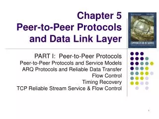
FLOW AND ERROR CONTROL The most important responsibilities of the data link layer are flow control and error control. Collectively, these functions are known as data link control. Flow Control Flow control refers to a set of procedures used to restrict the amount of data that the sender can send before waiting for acknowledgment. • ensure sending entity does not overwhelm receiving entity • by preventing buffer overflow • influenced by: • transmission time • time taken to emit all bits into medium • propagation time • time for a bit to traverse the link • assume here no errors but varying delays Error control in the data link layer is based on automatic repeat request, which is the retransmission of data.
Error Control • Detection and correction of errors such as: • lost frames • damaged frames • common techniques use: • error detection • positive acknowledgment • retransmission after timeout • negative acknowledgement & retransmission Automatic Repeat Request (ARQ) • collective name for such error control mechanisms, including: • Stop and Wait • Sliding Window • go back N • selective reject (selective retransmission)
11-3 PROTOCOLS Now let us see how the data link layer can combine framing, flow control, and error control to achieve the delivery of data from one node to another. The protocols are normally implemented in software by using one of the common programming languages.
11-4 NOISELESS CHANNELS Let us first assume we have an ideal channel in which no frames are lost, duplicated, or corrupted. We introduce two protocols for this type of channel.
Stop and Wait • source transmits frame • destination receives frame and replies with acknowledgement (ACK) • source waits for ACK before sending next • destination can stop flow by not send ACK • works well for a few large frames • Stop and wait becomes inadequate if large block of data is split into small frames
Stop and Wait • source transmits single frame • wait for ACK • if received frame damaged, discard it • transmitter has timeout • if no ACK within timeout, retransmit • if ACK damaged,transmitter will not recognize it • transmitter will retransmit • receive gets two copies of frame • use alternate numbering and ACK0 / ACK1 • pros and cons • simple • inefficient
Sliding Windows Flow Control • allows multiple numbered frames to be in transit • receiver has buffer W long • transmitter sends up to W frames without ACK • ACK includes number of next frame expected • sequence number is bounded by size of field (k) • frames are numbered modulo 2k • giving max window size of up to 2k - 1 • receiver can ack frames without permitting further transmission (Receive Not Ready) • must send a normal acknowledge to resume • if have full-duplex link, can piggyback ACks
Go Back N • based on sliding window • if no error, ACK as usual • use window to control number of outstanding frames • if error, reply with rejection • discard that frame and all future frames until error frame received correctly • transmitter must go back and retransmit that frame and all subsequent frames • Damaged Frame • error in frame i so receiver rejects frame i • transmitter retransmits frames from i • Lost Frame • frame i lost and either • transmitter sends i+1 andreceiver gets frame i+1 out of seq and rejects frame i • or transmitter times out and send ACK with P bit set which receiver responds to with ACK i • transmitter then retransmits frames from i
Go Back N - Handling • Damaged Acknowledgement • receiver gets frame i, sends ack (i+1) which is lost • acks are cumulative, so next ack (i+n) may arrive before transmitter times out on frame i • if transmitter times out, it sends ack with P bit set • can be repeated a number of times before a reset procedure is initiated • Damaged Rejection • reject for damaged frame is lost • handled as for lost frame when transmitter times out
Selective Reject • also called selective retransmission • only rejected frames are retransmitted • subsequent frames are accepted by the receiver and buffered • minimizes retransmission • receiver must maintain large enough buffer • more complex logic in transmitter • hence less widely used • useful for satellite links with long propagation delays
Utilization under SW Flow Control • Utilization = U = frame time / total time • U = 1/1+2a • a = Propagation Time / Transmission Time • a = Medium length in bits / Frame length in bits Station s1 sends f1 Station s2 sends an acknowledgment Station s1 sends f2 Station s2 sends an acknowledgment . . . Station s1 sends fn Station s2 sends an acknowledgment CALCULATION OF U
CALCULATION OF U • Total time to send the data=T=nTf • Tf=time to send and receive an acknowledgment • Tf=Tframe+Tprop+Tproc+ Tack + Tprop+Tproc • Tprop=propagation time from s1 to s2 • Tframe=time to transmit a frame • Tproc=processing time (negligible) • Tack=time to transmit an acknowledgment(very small as compared to data frame) • T=2Tprop+Tframe • For n frames T=n(2Tprop+Tframe) • Of that time only n x Tframe is actually spent transmitting data and the rest is overhead,therefore the utilization or efficiency of the line is • U= (n x Tframe )/n(2Tprop+Tframe) = Tframe/(2Tprop+Tframe) • If a=Tprop/Tframe then • U=1/(1+2a)
Utilization with Sliding Window Flow Control • N > 2a + 1 for • N < 2a + 1 for