Download
1 / 44
440 likes | 444 Views
HFT PIXEL Mechanics. HFT Review 25-Mar-2009 Wieman. PIXEL Work. Eric Anderssen Mario Cepeda Leo Greiner Tom Johnson Howard Matis Hans Georg Ritter Thorsten Stezelberger Xiangming Sun Michal Szelezniak Jim Thomas Chi Vu. ARES Corporation: Darrell Bultman Steve Ney Ralph Ricketts

E N D
HFT PIXEL Mechanics HFT Review 25-Mar-2009 Wieman
PIXEL Work • Eric Anderssen • Mario Cepeda • Leo Greiner • Tom Johnson • Howard Matis • Hans Georg Ritter • Thorsten Stezelberger • Xiangming Sun • Michal Szelezniak • Jim Thomas • Chi Vu ARES Corporation: Darrell Bultman Steve Ney Ralph Ricketts Erik Swensen
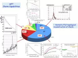
More precision, more D0 in a shorter time signal preserved with tight cuts when the precision is high combinatoric background reduced with tight cuts How does collection time scale with precision? Probably faster than linear
Pixel geometry. These inner two layers provide the projection precision End view 8 cm radius 20 cm 2.5 cm radius Inner layer Outer layer coverage +-1 One of two half cylinders total 40 ladders
Topics • Mechanical trade offs in achieving the highest pointing precision • Development work addressing mechanical precision and stability. • Mechanical construction and testing progress
r1 r2 perceived vertex true vertex m x x v v r1 r2 perceived vertex true vertex vertex projection from two points expectations for the HFT pixels pointing resolution = (13 19GeV/pc) m first pixel layer from coulomb scattering from detector position error more than 3 times better than anyone else detector layer 2 detector layer 1
Bob Connors Spiros Margetis Yifei Zhang development of spatial map Work has started on this program 10 gm touch probe force touch probe 2-3 m (xyz) and visual 2-3 m (xy) 50 m (z) active volume: huge visual sub micron (xyz) repeatability 5 m accuracy over active volume no touch probe active volume: 30 in X 30 in X 12 in MIMOSTAR3, 30 m pitch
Mechanical Stability Once the pixel positions are measured will they stay in the same place to within 20 µm? Issues that must be addressed: • Movement from temperature changes • Movement from humidity changes • Deflection from gravity • Vibration movement from mounts in STAR • Movement induced by cooling air • how much air is required • vibration and static displacement
Stability requirement drives design choices • The detector ladders are thinned silicon, on a flex kapton/aluminum cable • The large CTE difference between silicon and kapton is a potential source of thermal induced deformation even with modest 10-15 deg C temperature swings • Two methods of control • ALICE style carbon composite sector support beam with large moment of inertia • Soft decoupling adhesive bonding ladder layers
cable bundle drivers kapton flex cable pixel chips adhesive composite backer adhesive wire bonds capacitors Ladder design with soft adhesive (6 psi shear modulus) adhesive: 3M 200MP 2 mil, film adhesive
FEA analysis showing bi-metal thermally induced deformation ladder cross section short direction 20 deg C temperature change rigid bond 500 micron deformation soft adhesive 4.3 micron deformation
FEA analysis of thermally induced deformation of sector beam • FEA shell elements • Shear force load from ladders • 20 deg temperature rise • Soft adhesive coupling • 200 micron carbon composite beam • end cap reinforcement • Maximum deformation 9 microns (30 microns if no end cap)
FEA analysis - sector beam deformation – gravity load • FEA shell analysis • 120 micron wall thickness composite beam • gravity load includes ladders • maximum structure deformation 4 microns • ladder deformation only 0.6 microns
Air cooling of silicon detectors - CFD analysis • Silicon power: 100 mW/cm2 (~ power of sunlight) • 240 W total Si + drivers air flow path – flows along both inside and outside surface of the sector
Air cooling – CFD analysis stream lines with velocity • air flow velocity 9-10 m/s • maximum temperature rise above ambient: 12 deg C • sector beam surface – important component to cooling • dynamic pressure force 1.7 times gravity silicon surface temperature velocity contours
vibration modes – preliminary – better composite numbers available 224 Hz 348 Hz 229 Hz 473 Hz 316 Hz
The message Lots of complicated modes close in frequency End cap raises frequencies a bit vibration modes with reinforced end cap 259 Hz 441 Hz 276 Hz 497 Hz 397 Hz
wind tunnel setup to test vibration and displacement carbon fiber sector beam capacitance vibration probe two positions shown air in air out adjustable wall for air turn around air velocity probe two positions shown C:\Documents and Settings\Howard Wieman\My Documents\aps project\mechanical\PXL phase 1 sept 2008\sector ph1 wind tunnel.SLDASM
wind tunnel, rapid prototype parts from model air flow control parts built with 3D printer parts built with SLA, stereolithography apparatus
capacitive probe vibration measurements air velocity 2.7 m/s position signal, 25 m/volt log FFT, peak at 135 Hz air velocity 9.5 m/s position signal, 25 m/volt
Ladder vibration induced by cooling air no reinforcement at the end system resolution limit all errors desired vibration target required air velocity 18 mph
17 µm 17 µm 6 µm -167 µm 9 µm -179 µm 11 µm -248 µm 1 µm -156 µm -163 µm -113 µm measured static deformation from 9 m/s air flow open end reinforced end
4 µm 6 µm 6 µm 3 µm 3 µm 13 µm 14 µm 2 µm 14 µm 8 µm 4 µm 11 µm measured vibration (RMS) induced by 9 m/s air flow open end reinforced end
Vibration from STAR support, accelerometer measurement • detector vibration from STAR support < 0.1 micron RMS
Eric Anderssen and Tom Johnson have been working on fabrication methods for: Sector Beam and Ladders Produced sample beams, 244 m thick, 7 ply, 21 gm expected ladder mass 7.5 gm Development of sector beam and ladder fabrication ladders sector beam
(designed to allow ladder replacement) ladder to sector bond fixture for middle outer ladder finished, but not tested ladder to out2 bond fixture.SLDASM
sector chuck parts locating pin diamond MMC 8472A19.SLDPRT locating pin MMC 8472A11.SLDPRT ¼-20 x 1.5 in, 1 of 4 bullet nose liner MMC 31335A51, 1 of 3 bullet nose aligning pin MMC 31335A11, 1 of 2 z locator.SLDPRT ¼-20 x 1 in, 1 of 2 sector chuck out2 base.SLDPRT plunger pin 1lb MMC 3360A560, 1 of 2 sector chuck out2 cap.SLDPRT bullet nose diamond aligning pin MMC 31335A31 1.5 in post hex MMC 91780A361, 1 of 4
ladder chuck parts ¼-20 x 1in, 1 of 4 plunger pin 3 lb MMC 3360A330, 1 of 4 ladder chuck handle.SLDPRT, 1 of 2 ladder chuck.SLDPRT ladder chuck.SLDASM
out2 silk screen assembly for applying glue that holds ladder to the sector stainless surface 25 mil above aluminum surface this surface is initially shimmed by 20 mils to be 5 mils below the stainless surface. This is to permit future adjustment out2 silkscreen frame.SLDPRT sized for 2 mil bond line between stainless and aluminum
ladder assembly fixture vacuum chuck system for placing chips and other ladder parts 3/8 OD tube connection to vacuum vacuum distribution manifold vacuum release valve for hold down of the vacuum chucks ¾ ID tube connection to 1 gallon vacuum ballast tank
Full cylinder cooling test system in the shops, mostly SLA Only one sector shown out of full cylinder of 10 Will be populated with 1 sector with silicon heaters and the rest will have flex PC heaters 9 inch diameter tube mocks up ISC Thermal camera window and air stop not shown Have purchased and received air blower capable of > 300 CFPM at more than sufficient pressure Cooling tests will begin as soon as prototype sectors completed
conclusion - next major mechanical effort Build up full cylinder with heated dummy ladders and thermal test in a full size support cylinder with cooling air Check cooling and position stability
PIXEL Mechanical Service • One 6 inch air duct, possibly two • 300 CFPM cooling air flow • Total cooling system power: 1 kW • PIXEL power to be cooled: 240 watts
sensitivity to multiple coulomb scattering error in position from scattering at r detector layer 2 d2 m worst place for mass is at the first layer detector layer 1 r1 r r2 beam path dv true vertex perceived vertex