Download

1 / 18
180 likes | 409 Views
Thermo Fluid Design Analysis of TBM cooling schemes. M. Narula with A. Ying, R. Hunt, S. Park ITER-TBM Meeting UCLA Feb 14-15, 2007. Outline. Integrated thermo-fluid analysis capability at UCLA Analysis codes and peripherals CAE outlook for design analysis of complex components

E N D
Thermo Fluid Design Analysis of TBM cooling schemes M. Narula with A. Ying, R. Hunt, S. Park ITER-TBM Meeting UCLA Feb 14-15, 2007
Outline • Integrated thermo-fluid analysis capability at UCLA • Analysis codes and peripherals • CAE outlook for design analysis of complex components • Progress in the helium cooling solution for HCCB TBM • Focus on inlet/outlet manifold design for FW cooling • Future work • Further iterations on the design analysis of FW inlet/outlet manifold for helium • Extension of cooling circuit to include breeder zone and associated manifolds • Design of the common helium distributor manifold
Thermo Fluid Analysis System(A complete 3D CAE system) • MCAD: CATIA, SolidWorks • CAD translator: CADthru • CFD/Thermo-Fluid Solvers: SC/Tetra, CFdesign • Communicator: FLDUTIL • Stress Analysis system: ANSYS, ABAQUS The CAE system helps quick evaluation of critical parameters like the coolant distribution, circuit pressure drop, structural temperature, structure stress distribution and associated deformation, etc. in a particular design concept. Several iterations through the design analysis cycle can help generate the optimal cooling scheme.
Coolant circuit pressure CATIA CAD CFdesign is a new addition to the thermo-fluid solvers at UCLA, it has direct CAD integration with CATIA Thermo fluid analysis of the proposed water cooling scheme for ITER shield blanket module 7. The CAD model from CATIA is directly associated with the FE model in CFdesign
Coaxial Coolant Distributor for ITER blanket modules In Out Out Out In In CFD analysis in complex geometric flow volumes can be performed with CFdesign
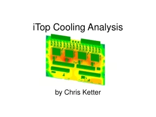
HCCB TBM FW cooling evaluation Ferritic steel Surface heat flux 0.3MW/m2 Beryllium (2mm) Deformation Design analysis cycle for the HCCB TBM cooling solution MCAD (SolidWorks)-> Thermo-Fluid Analysis (SC/Tetra)-> Structural Analysis (ANSYS)
Validation study Progress in HCCB Helium cooling scheme • Validation studies were performed to select the best set of mesh and CFD analysis parameters against existing correlations. • HCCB helium cooling circuit CFD analysis was extended to include the top and bottom breeder zone caps. • A 1/6 poloidal model of the HCCB cooling circuit with FW and breeder zone cooling channels was analyzed. • Emphasis was placed on design analysis of the FW helium inlet and outlet manifolds to ensure uniform coolant distribution in the FW channels.
Helium flow path in the validation model Heat transfer coefficient on channel walls Structure temperature in validation model Average h from Dittus Boelter correlation: 2779 W/m2K Validity range of log law: Effect of mesh resolution at the flow channel walls on numerical results Two layers of prismatic elements were placed in the fluid domain at the fluid-solid interface . The mesh resolution in the table corresponds to the size of the wall prismatic elements. The logarithmic law of the wall was used to calculate turbulent heat transfer at the walls.
FW and ferritic structure temperature along with temperature distribution in the helium coolant Helium inlet at 8.0 MPa and 573K at a flow rate of 0.32 kg/s FW Surface heat flux at 0.3MW/m2 Compressible turbulent flow with RNG k-e model
A 1/6 poloidal model of the helium cooling circuit with the FW cooling channels and the breeder zone cooling. The analysis is being extended to include the entire helium cooling circuit for the HCCB TBM in near future.
Evolution of helium inlet manifold designs for FW cooling Design 1 Design 2 Design 3 Design 4 Design 5 Design 6
Helium inlet at 8MPa, 573K @ 0.32 kg/s FW Heat Flux: 0.3 MW/m2
Design 5 Be wall temperature Helium inlet at 8MPa, 573K @ 0.32 kg/s FW Heat Flux: 0.3 MW/m2 Manifold velocity Velocity distribution in the inlet/outlet manifold design 5 along with the temperature distribution on the beryllium first wall. The temperature hot spot has moved from the bottom to the middle of the wall, indicating a less coolant flow in the central channels. The temperature distribution is symmetric as opposed to design 4.
Design 6 Be wall temperature Helium inlet at 8MPa, 573K @ 0.32 kg/s FW Heat Flux: 0.3 MW/m2 Manifold velocity A direct bleed was opened for the central channels to increase coolant flow rate in design 6. The effect can be seen by a reduction in the central hot spot in the beryllium layer. Additional optimization of the inlet manifold will be carried out.
The Beryllium wall centerline temperature poloidal variation Design 5 Design 6 The hot spot in the center has been reduced in design 6. The temperature distribution has to be made more uniform. The alternative hot and cold bands correspond to the hot and cold legs of the three pass cooling channel design
Near term tasks • Thermo-fluid analysis of the complete Helium flow circuit in the HCCB design including breeder region. • Effort has started for the conceptual design and corresponding thermo-fluid design analysis of the common distribution and collection manifold for HCCB sub-modules. Common manifold