Download
1 / 27
300 likes | 441 Views
Self consistent ion trajectories in electron shading damage. T.G. Madziwa, F.F. Chen & D. Arnush UCLA Electrical Engineering ltptl November 2002. Abstract.

E N D
Self consistent ion trajectories in electron shading damage T.G. Madziwa, F.F. Chen & D. Arnush UCLA Electrical Engineering ltptl November 2002
Abstract In electron-shading damage, the photoresist is charged negatively, preventing electrons from entering the trench, while ions are accelerated toward the bottom of the trench. We have numerically calculated the effect of these fields on the ion trajectories. The ions are injected at acoustic speed from a sheath edge far from the substrate, and the electrons have a Maxwell-Boltzmann distribution. The photoresist and trench walls are assumed to be insulators, and the trench bottom a conductor at various potentials relative to the sheath edge. The potentials on all surfaces are given initial values, and a Poisson solver is used to compute the electric field everywhere. The ions’ trajectories in this field are then computed. Setting the flux of ions to each dielectric surface equal to the Maxwellian electron flux yields a new value of the surface charge. The E-fields and trajectories are then recomputed, and the process iterated until the values converge. It is found that the E-field is concentrated near the entrance to the trench, the only place where the charges matter. The ions receive a kick there and then coast the rest of the way. Thus the trajectories are very sensitive to the exact shape of the photoresist and will change as the etch progresses.
sheath Hashimoto et al. JJAP 1994 Motivation 1. Verification of the physical picture of electron shading damage mechanism. New result: ion orbits are ballistic inside the trench and are determined by fields at the entrance There are no significant numbers of ions that hit the sidewalls.
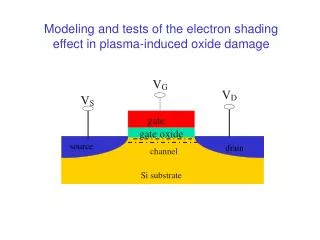
Methodology 1 • Define space with dielectric and trench, and metal collector. • Define sheath edge. • Assume ions are emitted from sheath edge with directed velocity cs. • Assume electrons are Maxwellian everywhere. • Assume j = 0 on dielectric surfaces. This causes the plane surface to charge to –15.5 V, according to the plane floating potential formula. • On the trench walls, potential will self-adjust so that the ion and electron fluxes are equal.
Methodology 2 • Ion flux depends on the E-field in trench, which depends on wall potential. • We use a 2D Poisson solver to get E-fields for given boundary potentials and then calculate the ion orbits in this E-field. • We then iterate until the potential distribution and ion orbits converge to a stable solution. • Initially, the walls are assumed to be a potential that gradually changes from the one on the dielectric to the one on the collector. • To avoid a singularity when no ions are collected in a cell, we approximate that to be 0.1 ion received. This makes an empty bin much more negative (~-40V) than bin with one ion.
L W S y4 HS collector y3 Dielectric material y2 y1 x1 x3 x4 x1 Vacuum region Setup II • The purple region is the region of interest and it lies in the plasma sheath • Ions (Nions) are emitted from the plasma-sheath boundary with the Bohm velocity • We count the ions that fall in the vertical and horizontal bins diagram is upside down
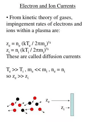
Current densities The ion current densities per bin: The electron current density: where Vx is the potential in bin x and is the random velocity of the electrons. The condition for surface voltage calculation is that:
Scale Invariance I • Our simulations were done in mm dimensions. • We want to show that by going down to more realistic dimensions, the results remain valid. • We look at the invariance of the Poisson solution, scaling of the time of flight of ions and the equation of motion. • We look at the case where all lengths are scaled by a uniform factor W HS
For, s << lD we can solve Laplace’s equation: subject to the boundary conditions: Scale Invariance II Start with Poison’s equation: Define: Then: Let s be the scale length of the gradient , and define , so that Now we have:
Ion trajectories: AR=7, -26V bias A few ions can hit the sidewall here Inside the trench, the ions go in straight paths ions bend at the entrance to the trench
Sidewall ions AR=5, -26V bias Ion orbits appear to be straight inside the trench
Sidewall ions AR=5, -26V bias Aspect ratio: 5 to 1 Bias: -26 Volts Scale: 80 to 1 With increased magnification, ion orbits also cross
Trajectories AR=3, -22V The ions bend a lot more with AR=3 and so more ions fall on the sidewalls.
AR=7:1 AR=5:1 AR=3:1 Sidewall ions -26V bias
Why more sidewall ions at lower AR? AR=7 -26V No sidewall ions Answer lies in distribution of equipotential lines. AR=3 -22V Sidewall ions
Collector Ions: AR = 3 All aspect ratios follow the same trend.As |V| increases, so does the ions on collector… (and sidewall ions decrease)
Monotonic increase/decrease 2 limit cycle Chaos 3 limit cycle Damping oscillations Limit cycles: isolated periodic solutions • A typical simulation will come to one of these types of solutions (and some more types not shown here): a limit cycle when the trajectory repeats itself
3 limit cycle: 62 ions, 56 ions, 34 ions Sidewall ions at AR=5 -18V bias:
Case 1: straight edges Case 2: arc at entrance Dependence on overall structure • Not much change in the number of ions deposited on sidewalls. • With the rounded edges, there are significantly more ions on the collector than with the sharp corners.
KnL01, case b: kink not too close to trench opening Case a: no kink KnL02, case c: kink close to trench opening What about a minor change in structure like a kink on surface?
Case Case a b c Sidewalls 0.29% 0.29% 0.15% 0.15% 1.8% 1.8% Collector 11% 11% 9.6% 9.6% 10% 10% arc 17.5% 17.5% 15.3% 15.3% 13.5% 13.5% Kinks on surface with a bias of –18V • A tiny kink on surface gives rise to ion distribution changes • A small kink on the surface changes the sidewall profiles much more than a complete change in structure. (compare with the case of an arc versus straight edges) • A kink close to the opening of the trench increases sidewall ions from a max of 0.29% to 1.8%
Inside the metal trench, Inside the trench Sheath region AR=5, -60V bias, 2 bins in metal
Effect of neighboring trenches • More sidewall ions when there are adjacent trenches • Ions collected are symmetrical (just like the geometry) • More ions are collected on the inner walls
Ion shadowing effect Double trench, AR=5, -22V bias
Conclusions • insignificant number of ions hit the wall with single trenches. • Ions drift freely inside trench once their orbits are set by the fields at the entrance. • Fewer ions hit the wall at high potentials because of the large acceleration. • Fewer ions hit the sidewall at large aspect ratio because the field lines are straighter. • Fewer sidewall ions with large collectors because the field lines are straighter. • There are still too few ions hitting the sides to change the etching profile.