Download
1 / 44
460 likes | 581 Views
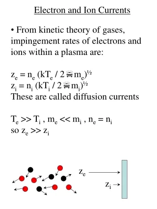
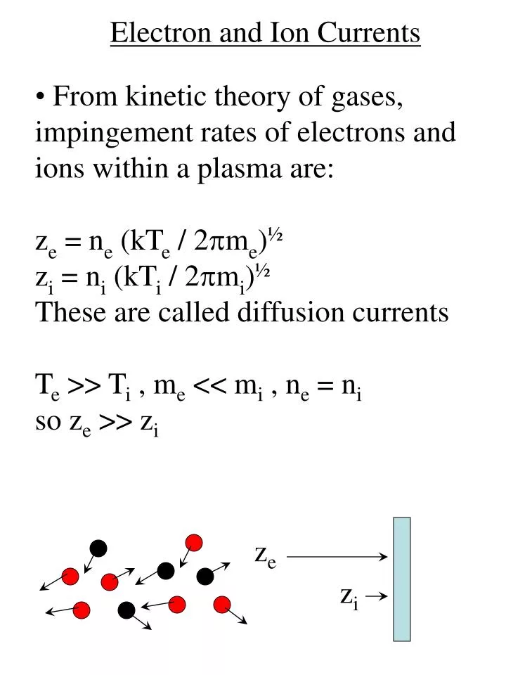
Electron and Ion Currents. From kinetic theory of gases, impingement rates of electrons and ions within a plasma are: z e = n e (kT e / 2 p m e ) ½ z i = n i (kT i / 2 p m i ) ½ These are called diffusion currents T e >> T i , m e << m i , n e = n i so z e >> z i. z e. z i.

E N D
Electron and Ion Currents • From kinetic theory of gases, impingement rates of electrons and ions within a plasma are: • ze = ne (kTe / 2pme)½ • zi = ni (kTi / 2pmi)½ • These are called diffusion currents • Te >> Ti , me << mi , ne = ni • so ze >> zi ze zi
Electron and Ion Currents • For example, • ne = ni = 1010 cm-3 • Te = 23000 K • Ti = 500 K • Then ze = 2.35 x 1017 cm-2s-1 • Je = eze = 37.6 mAcm-2 • zi = 1.28 x 1014 cm-2s-1 • Ji = ezi = 0.0205 mAcm-2 Je = 37.6 mAcm-2 Ji = 0.0205 mAcm-2 Je >> Ji
Steady-State • No net current can flow through an insulator • Negative charge will build-up on the object repelling electrons and attracting ions (drift currents develop) • A steady-state is achieved when the electron and ion currents are equal diffusion currents (initial) Je = eze Insulated object Ji = ezi diffusion + drift currents (steady-state) - - - - - - eGe Insulated object eGi E
Sheath Region • A positive space-charge region is created that is depleted of electrons, leaving predominantly gas atoms and ions (e.g., Ar, Ar+). • This region is called the sheath region and is similar to the depletion region formed in a semiconductor device such as a p-n junction diode - - - - - - ne Insulated object Sheath region
Dark Spaces • The sheath regions are also called “dark spaces” due to their visual appearance • Fewer electrons result in less optical emission from Mahan, colorplate VI.18
Sheath Currents • At steady-state the impingement rates at the surface are: • For electrons, Ge = -meneE – Dene • For ions, Gi = miniE – Dini • = mobility D = diffusion coefficient Drift Term Diffusion Term - - - - - - eGe Insulated object eGi E
Sheath Currents • In 1-D, = d/dx, giving: • For electrons, Ge = – meneE – Dedne/dx • For ions, Gi = miniE – Didni/dx • Using ni = ne = n at the edge of the plasma sheath and Ge = Gi (steady-state) gives: • – menE – Dedn/dx = minE – Didn/dx • Solving for E gives: • E = [(dn/dx)/n] [ (Di – De) / (mi + me) ] - - - - - - eGe Insulated object eGi E
Sheath Currents • Substituting this expression for E into the ion flux equation gives: • Gi = – Da dni/dx • Da = (miDe + meDi)/(me + mi) • (ambipolar diffusion coefficient) • Since me >> mi, we have • Da = Di + (mi/me)De
Sheath Currents • Next we can use the Einstein relation between mobility and diffusion, D/m = kT/q, to give: • Da = Di (1 + Te / Ti) • Since Te >> Ti, we have • Da = DiTe/Ti • We see that Da >> Di
Sheath Currents • The effect of the electrons is to establish an electric field that pulls the ions and increases it’s effective diffusion from Di (the unaided diffusion at E = 0) to Da • This effect is known as ambipolar diffusion - - - - - - eGe Insulated object eGi E
Sheath Currents • The ion current increases to • Gi~ ni √(kTe/mi) • For example, for ni = 1010 cm-3, Te = 23000 K, and Ar gas, we have • Gi = 2 x 1015 cm-2s-1 • eGi = 0.35 mA/cm2 • The enhanced ion current is much greater than the unaided diffusive flux calculated previously (ezi = 0.0205 mAcm-2) • Gi ~ surface atom density in 1 sec
Growth Rate Example Gi ~ 1 mAcm-2 = 6.2 x 10¹⁵ ions s-1cm-2 Y (1 keV Ar+ ions on Al) ~ 1.5 Sputter rate of Al = 9.3 x 10¹⁵ atoms cm-2s-1 Surface density of Al = 6.07 x 10²² atoms cm-3 The deposition rate would be 15 Å s-1 = 5.4 mm/hr
Plasma Potential • Since charged particles are abundant in the plasma, it is a fairly good conductor • The plasma is at an equipotential, Vp, called the plasma potential Insulated object Vp ? sheath region plasma body
Floating Potential • An insulating object placed in a plasma will develop a negative charge • A “floating potential develops” (Vf) until steady-state is achieved (Ge = Gi) Insulated object Vp - - - Ge Vf Gi
Floating Potential Insulated object Vp - - - Ge Vf Gi • M-B distribution of energies: • Gi = Ge = ze exp [ -e (Vp – Vf)/kTe ] • Rearranging gives • Vp – Vf = (kTe/e) ln ( ze / Gi ) • = (kTe/2e)ln(mi/2pme) • e.g., if Te = 23000 K, eze = 37.6 mAcm-2, and eGi = 0.35 mAcm-2 as calculated previously then Vp – Vf = 9.3 V
Conducting Surfaces • A conducting surface at the plasma potential draws the diffusion currents Plasma Potential Cathode Vp Va = Vp ze > zi Va eze ezi • A conducting surface at the floating potential draws no net current Floating Potential Cathode Vp eGe Va = Vf Ge = Gi Va eGi
Saturation Regions (Conducting Surfaces) “Ion saturation” regime Va << Vp: all electrons are repelled Vp - - - - - Va eGi= 0.35 mAcm-2 “Electron saturation” regime Va >> Vp: all ions are repelled + + + + + eze = 37.6 mAcm-2 Va Vp
“Diode” Plasma • Since the electron current is much greater than the ion current, an I-V curve of a conducting surface in the plasma shows rectifying behavior • Hence, the term “diode” plasma from Manos, Fig. 18, p. 31
Langmuir Probe • Can measure I-V curve of plasma using a Langmuir probe from Mahan, colorplate VI.18
Langmuir Probe • From the measured I-V curve, can determine : • Floating potential • Plasma potential from Manos, Fig. 18, p. 31
Conducting Surfaces “Electron Retardation” Regime J< = eGi - eze exp [ -e (Vp – Va)/kTe ] from Manos, Fig. 18, p. 31
Langmuir Probe • Electron temperature, • Te ~ e / [ k dln(J)/dV ] • = 47 840 K from Mahan, Fig. VI.7, p. 166
Langmuir Probe • Electron density can be determined from diffusion current: • ne = (eze) / [e(kTe / 2pme)½ ] • = 5.1x109 cm-3 from Mahan, Fig. VI.7, p. 166
Cathode Fall • The sheath region has low conductivity • Most of the applied potential is dropped across the cathode sheath • Cathode fall ~ Va ~ breakdown voltage cathode Vp - cathode fall V = Va
Cathode Fall • The cathode fall is the kinetic energy gained by ions striking the cathode and of secondary electrons entering the plasma (ignoring collisions in the sheath) • Cathode fall ~ 100’s Volts electrons ions cathode Vp - cathode fall V = Va
Energy Distribution of Sputtered Particles • The sputtered particle energies are much greater than thermal energies • This helps in producing conformal films from Powell, Fig. 2.9, p. 33
Sheath Width • What is the width of the sheath region ? Cathode Vp Va sheath region plasma body
Sheath Width • The width of the sheath (depletion region) can be estimated by calculating the potential that results from a test charge placed within the plasma from Manos, Fig. 2, p. 189
Sheath Width • The charge creates a potential, which in free space (no plasma) would be: • Vo(r) = e / (4peor) • r = distance from the test charge
Sheath Width • The potential in the plasma may be determined by solving Poisson’s equation: • 2V(r) = – r(r)/eo • 2 = Laplacian operator
Sheath Width r(r) = local charge density = e [ ni(r) – ne(r) ] Boltzmann’s law: ne(r) = ne exp [ eV(r) / kTe ] ~ ne [ 1 + eV(r) / kTe ] ni(r) ~ ni since ions are too slow to respond relative to the electrons ni, ne = n = plasma density r(r) ~ – (e2n/kTe) V(r)
Debye Length • 2V(r) = - (e2n/eokTe) V(r) • Solving gives, • V (r) = Vo exp (-r/LD) • LD = Debye length • = (eokTe / e2n)½
Debye Shielding • In free-space, Vo(r) = e / (4peor) • In a plasma, V(r) = Vo exp (-r/LD) • The plasma electrons rearrange to shield the potential causing its attenuation with a decay length equal to LD • The plasma is expelled within a region ~ LD (sheath region) Unscreened potential Vo(r) = Q / (4peor) Q Shielded potential V(r) = Voexp(-r/LD) r
Debye Length • LD = Debye length • = (eokTe/e2n)½ • = 6.93 [ Te(K) / ne (cm-3) ] ½ • = 743 [ Te(eV) / ne(cm-3) ] ½ • For example, for Te = 1 eV, ne = 1010 cm-3, we get LD = 74 mm
Child’s Law • A more exact treatment for a planar surface (cathode) gives: • Ls = (4eo/9eGa)½(2e/mi)¼(Vp-Va)¾ • Substituting Gias determined previously gives: • Ls ~ 0.8 ¾ LD • = e(Vp - Va)/ kTe • Hence, the sheath thickness is on the order of 10’s of LD (mm’s) • Electrode spacing ~ cm’s
Cathode Fall from Mahan, colorplate VI.18
Plasma Reactions Homogeneous Reactions (occur within the plasma) Heterogeneous Reactions (occur on a surface)
Homogeneous Reactions • Reactions that occur within the plasma • Excitation : • Electrons produce vibrational, rotational, and electronic states leaving the atom or molecule in an excited state • e- + O2 e- + O2* • e- + Ar e- + Ar* • e- + O e- + O* • Glow discharge: • O2* O2 + hn • O* O + hn
Homogeneous Reactions • Ionization : • Responsible for ion & electron formation which sustains the plasma • Produces ions for sputtering • e- + Ar Ar+ + 2e- • e- + O2 O2+ + 2e-
Homogeneous Reactions • Dissociation : • A molecule is broken into smaller atomic or molecular fragments (radicals) that are generally much more chemically active than the parent molecule • This is important in reactive sputtering (e.g., reactive ion etching) and plasma-enhanced CVD • e- + O2 O + O + e- • e- + CF4 e- + CF3* + F*
Heterogeneous Reactions • Reactions that occur on the surface • Sputtering • Secondary electron emission • Reactive etching/deposition
Reactive Ion Sputtering (Deposition) • Excited species (particularly radicals) can react with the surface to deposit nitrides and oxides Reactive sputter deposition : From Ohring, p. 126
Reactive Ion Etching (RIE) • A reactive gas (e.g., N2, O2, CF4) is mixed with the inert gas (e.g., Ar) • The reactive gases are broken down in the plasma into ions, fragments, radicals, excited molecules, etc. from Powell, Fig. 3.18, p. 77
RIE • Acceleration of ions across sheath region results in anisotropic etching Wet chemical etching Plasma etching Ion bombardment adapted from Manos, Fig. 8, p. 12


![Electron [and ion] beam studies of magnetic nanostructures](https://cdn2.slideserve.com/4692681/slide1-dt.jpg)