Download
1 / 26
340 likes | 609 Views
Surveying. Chapter Three COMPASS TRAVERSING Dept Of CIVIL ENGINEERING. SYLLABUS. Objectives: Use the survey instruments. Take linear and angular measurements. Measure the area of land. Prepare layouts and maps. Set out alignments for roads, railways, canals, pipelines, tunnels etc.

E N D
Surveying Chapter Three COMPASS TRAVERSING Dept Of CIVIL ENGINEERING
Objectives: • Use the survey instruments. • Take linear and angular measurements. • Measure the area of land. • Prepare layouts and maps. • Set out alignments for roads, railways, canals, pipelines, tunnels etc. • Prepare contour map. • Compute area and volume from given contour map.
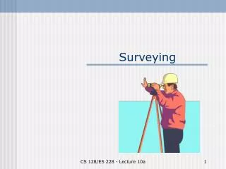
SURVEYING COMPASS TRAVERSING COMPASS SURVEY… • In order to get the location of a point in surveying on, above or below the surface of the earth, it is necessary to know its distances from a point / station along a line whose direction is known.
SURVEYING COMPASS TRAVERSING Fundamental Concepts The direction of a line is defined by a horizontal angle with respect to a reference line. Depending on the type of reference, the direction of the line is termed as relative or absolute. In relative direction, the reference line does not remain fixed over time. • Meridian The reference line with respect to which horizontal angle of survey line are measured is known as meridian. There are different types of meridians based on the type of reference. • True Meridian • Magnetic Meridian • Grid Meridian • Arbitrary Meridian
SURVEYING COMPASS TRAVERSING True Meridian • The true meridian is the (imaginary) line of intersection of a (imaginary) plane passing through the geographical North and South poles of the earth with its actual surface. • The direction of true meridian at any station is constant and hence, direction of a line with reference to this remains same over time. • At any station, it can be determined through Astronomical survey. For any engineering works of importance, the direction of at least one line is determined with true meridian as reference.
SURVEYING COMPASS TRAVERSING Magnetic Meridian • The magnetic meridian at a station on surface of the earth is the (imaginary) line of intersection of a (imaginary) plane passing through the magnetic North and South poles of the earth with its actual surface. • The direction of a freely suspended well balanced magnetic needle provides the magnetic meridian at a station. • As the magnetic poles of the earth changes with time and so the magnetic meridian at any station. Thus, the direction of a line with reference to magnetic meridian varies with time. Magnetic meridian is employed as a line of reference for rough surveys.
SURVEYING COMPASS TRAVERSING Meridians…….. • Convergence of meridian : Meridians on the surface of the earth converge towards each other as the distance from the equator towards either of the poles increases. • Arbitrary Meridian Any convenient direction from a survey station to some well defined permanent object is known as arbitrary meridian. This is used for small area survey or to determine the relative directions of small traverse. • Relative Direction The direction of a line is expressed in different ways depending upon the type of survey. It is depicted by bearing, included angle, deflection angle etc. These quantities may be observed directly in the field or can be obtained indirectly by computation.
SURVEYING COMPASS TRAVERSING Bearing • The horizontal angle measured in clockwise or anticlockwise direction between the meridian and the survey line is termed as bearing. Different types of bearings are defined based on different criteria. • Based on meridian Azimuth or True Bearing, Magnetic Bearing, Grid Bearing, Arbitrary Bearing • Based on direction: Fore Bearing, Back Bearing • Based on disignation Whole circle bearing, Quadrant bearing (or Reduced bearing)
SURVEYING COMPASS TRAVERSING Azimuth or True Bearing • The azimuth or true bearing of a line is its horizontal angle from the North direction of the true meridian measured clockwise. • In Figure 19.2, azimuth of a line OA is given by NOA (= 52°), measured from the North (Geographical) and that of line OB is NOB (= 208°).
SURVEYING COMPASS TRAVERSING Magnetic Bearing • The horizontal angle which a line makes with the magnetic meridian measured from Magnetic North line is called magnetic bearing. It varies with time. Magnetic meridian of a line can be measured in the field by using prismatic compass (Figure 19.3).
SURVEYING COMPASS TRAVERSING Arbitrary Bearing The horizontal angle of a line measured with respect to an arbitrary meridian is called arbitrary bearing. • Based on the Direction Any straight line has two diametrically opposite directions. The direction in which a survey work proceeds is known as forward direction and the opposite direction is known as backward direction. Thus, there are two types of bearing depending upon the direction of the line for which it is being is determined. • Fore Bearing • Back Bearing
SURVEYING COMPASS TRAVERSING Fore bearing • The bearing of a line measured in the forward direction (i.e., along the progress of survey) is known as fore bearing. • In Figure fore bearing of the line AB is given by NOB. • Fore bearing = Back bearing ± 180°
SURVEYING COMPASS TRAVERSING Back Bearing • The bearing of a line measured in the backward direction (i.e., opposite to the direction of progress of survey) is known as back bearing. • In Figure 19.5 the back bearing of the line AB is NOA (= 223°). NOA is also called bearing of the line BA. • Back Bearing = Fore Bearing ± 180
SURVEYING COMPASS TRAVERSING Designation of Bearing • The angle representing bearing is designated depending on the measurement of the angle either in clockwise and anti-clockwise direction measured either from the North or from the South limb whichever provides minimum angle. • Whole circle bearing • Quadrantal bearing (or Reduced bearing)
SURVEYING COMPASS TRAVERSING The whole circle bearing (W.C.B) • The whole circle bearing (W.C.B) of a line is the horizontal angle measured clockwise from the North limb of the meridian. It varies from 0° to 360°. • In Figure 19.6, The whole circle bearing (W.C.B) of the line OA is 52° and that of line OB is 208°.
SURVEYING COMPASS TRAVERSING Quadrantal Bearing (or Reduced Bearing) • The quadrantal bearing (Q.B.) also known as reduced bearing (RB) of a line is defined by the acute angle which the line makes with the meridian. Thus, it depends on the quadrant in which the line presents. It is measured in clockwise or anti-clockwise direction either from the North or from the South limb of the meridian whichever is nearer and thus provides minimum angle. • The quadrantal bearings of different lines OP, OQ, OR and OS are respectively, can be given as N 40°E, S49° E, S72° W, and N31° W. In all cases, values of bearing of angles lie between 0° and 90°. • Thus, reduced bearing of a line is designated by the direction from which it is measured (i.e., either N for North or S for South) followed by the value of the angle at the end, the direction to which it is measured (i.e., either E for East or W for West).
SURVEYING COMPASS TRAVERSING
SURVEYING COMPASS TRAVERSING Conversion of WCB to RB .
SURVEYING COMPASS TRAVERSING Local Attraction • In presence of magnetic materials, the magnetic needle deviates from the magnetic meridian and thus provides wrong direction of a line. The deviation arising from such local sources is called local attraction. If the fore bearing and back bearing of a line does not differ by 180°, then there is a possibility of local attraction during the observation of the line. Otherwise, if the sum of the interior angles of a closed traverse does not provide (2n - 4) right angles [where n is the number of sides in the traverse], then there is a possibility of local attraction during the observation of the traverse. • Determination of Angles/ Directions. Direction and thus angles can be determined by means of a tape, plane-table, alidade, sextant, or compass etc but normally these are measured with a transit theodolite. In this module, measurement of angles using theodolite has been considered.
SURVEYING COMPASS TRAVERSING Ex19-2 Following are the observed magnetic bearings of the traverse legs: At what stations local attraction is suspected? Determine the correct bearings of the traverse legs and also calculate the included angles. The FB of the lines are given in reduced bearing. Their equivalent WCB are
SURVEYING COMPASS TRAVERSING • The FB and BB of any line differs exactly by 180°, if the stations are free from local attraction. In the given observation, the FB and BB of the line AB differs by 180° and thus stations A and B are free from local attraction. The bearing of the lines observed at stations A and B may be considered to be correct. • Given, FB of BC = 78° 15' • Therefore Correct, BB of BC = 78° 15' + 180° = 258° 15' • But, observed BB of BC = 256° 00' • Therefore Error at C = 258° 15' - 256° 00' = - 2°15' • Correction at C = 2° 15' • Observed FB of CD = 300° 30' • Correction at C = + 2° 15' • Therefore corrected FB of CD = 302° 45' - 180° = 122° 45' • and corrected BB of CD = 125° 15' • Error at D = + 2° 30' • or Correction at D = - 2° 30' • observed FB of DA = 210° 15' • Therefore corrected FB of DA = 210° 15' - 2° 30' = 207° 45' • and corrected BB of DA = 207° 45' - 180° = 27° 45' (Checked)
COMPASS TRAVERSING • Included angle As the traverse is running anti-clockwise the included angle will be the interior angles. Angle at A = F.B. of AB - B.B. of DA = 120° 30' -27° 45' = 92° 45' B = F.B of BC - B.B of AB = 78° 15' - 300° 30' = - 222° 15' + 360° = 137° 45' C = F.B of CD - B.B of BC = 300° 30' - 256° 00' = 44° 30' D = F.B of DA - B.B of CD = 210° 15' - 125° 15' = 85° 00' • Calculation of Bearing (2nd method) Bearing of the line AB = 120° 30' (correct) B = 137° 45' Bearing of the line BC = 258° 15' - 180° = 78° 15' (since traverse is anti-clockwise) C = + 44° 30' 122° 45' Bearing of the line CD = 122° 45' + 180° = 302° 45' D = + 85° 00' 387° 45' Bearing of CD = 387° 45' - 180° = 207° 45' A = + 92° 45' 300° 30' Bearing of AB = 300 30' - 180 = 120 30' (checked)
SURVEYING COMPASS TRAVERSING [Note : In any traverse, running anti-clockwise, included angle at any stations = F.B. of the forward line - B.B. of the backward line].
References: • Surveying and Levelling N. N. Basak • Surveying and Levelling Part I and II T .P. Kanetkar & S. V.Kulkarni • Text book of Surveying S.K.Husain M.S. Nagaraj