Download
1 / 76
760 likes | 933 Views
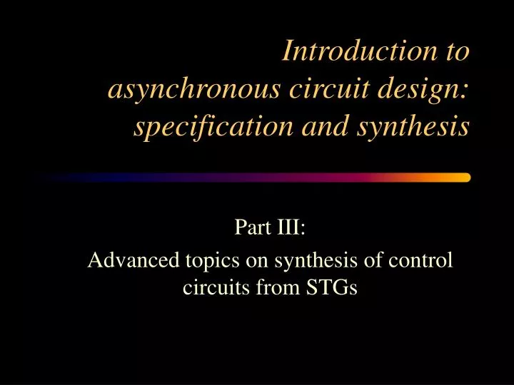
Introduction to asynchronous circuit design: specification and synthesis. Part III: Advanced topics on synthesis of control circuits from STGs. Outline. Logic decomposition Hazard-free decomposition Signal insertion Technology mapping Optimization based on timing information

E N D
Introduction toasynchronous circuit design: specification and synthesis Part III: Advanced topics on synthesis of control circuits from STGs
Outline • Logic decomposition • Hazard-free decomposition • Signal insertion • Technology mapping • Optimization based on timing information • Relative timing • Timing assumptions and constraints • Automatic generation of timing assumptions
Specification(STG) Reachability analysis State Graph State encoding SG withCSC Design flow Boolean minimization Next-state functions Logic decomposition Decomposed functions Technology mapping Gate netlist
No Hazards abcx 1000 b+ 1 1 0 0 a 1100 x 1 1 0 1 0 b a- c 0 0 0 1 0100 c+ 0110
abcx 1000 1 0 b+ a z 0 0 1100 b x c a- 0 0100 1 0 0 1 0 1 1 0 1 0 c+ 1 1 1 1 1 0 0 0 1 0 0110 0 0 0 1 1 Decomposition May Lead to Hazards 1000 1100 1100 0100 0110
Decomposition • Acknowledgement • Global acknowledgement • Generating candidates • Hazard-free signal insertion • Event insertion • Signal insertion
d- b+ d+ y+ a- y- c+ d- c- d+ z- b- z+ c+ a+ c- c z b a a y b d Global acknowledgement
d- b+ d+ y+ a- y- c+ d- c- d+ z- b- z+ c+ a+ c- c z b a a y b d How about 2-input gates ?
d- b+ d+ y+ a- y- c+ d- c- d+ z- b- z+ c+ a+ c- How about 2-input gates ? c z b a a y b d
d- b+ d+ y+ a- y- c+ d- c- d+ z- b- z+ c+ a+ c- How about 2-input gates ? 0 c 0 z b a a y b d
d- b+ d+ y+ a- y- c+ d- c- d+ z- b- z+ c+ a+ c- How about 2-input gates ? c z b a a y b d
d- b+ d+ y+ a- y- c+ d- c- d+ z- b- z+ c+ a+ c- a b How about 2-input gates ? c z y d
Strategy for logic decomposition • Each decomposition defines a new internal signal • Method: Insert new internal signals such that • After resynthesis, some large gates are decomposed • The new specification is hazard-free • Generate candidates for decomposition using standard logic factorization techniques: • Algebraic factorization • Boolean factorization (boolean relations)
y- y- 1001 1011 z- w- 1000 0001 w+ y+ w- z- x+ z- w- w+ 1010 0000 0101 0011 w- y+ x+ z- y+ x+ x- 0010 0100 x- x+ y+ z+ 0110 0111 z+ Decomposition example
x y- y w 1001 1011 z z- w- y 1000 0001 w+ z y+ x w- z- x+ w 1010 0000 0101 0011 w w- y+ x+ z- C z y z 0010 0100 x- x+ y+ y z+ C 0110 0111 x z y yz=0 yz=1 y- 1001 1011 z- w- 1000 0001 w+ y+ w- z- x+ 1010 0000 0101 0011 w- y+ x+ z- 0010 0100 x- x+ y+ z+ 0110 0111
x w y z x w w C z y z y C x z y s=1 y- s 1001 1011 z- s- w+ 1001 1000 z- s- y+ w- 0011 1000 0001 1010 y+ s- w- z- x+ x- 1010 0000 0101 w- y+ x+ z- 0111 0010 0100 s+ x+ y+ s=0 z+ 0111 0110
s=1 y- y- 1001 1011 z- s- s- w+ 1001 1000 z- s- y+ w- z- w- w+ 0011 1000 0001 1010 y+ s- w- z- x+ x- 1010 0000 0101 y+ x+ x- w- y+ x+ z- 0111 0010 0100 s+ s+ x+ y+ z+ s=0 z+ 0111 0110
x 1001 y- y w 1001 1011 z z- w- y 1000 0001 w+ z y+ x w- z- x+ w 1010 0000 0101 0011 w w- y+ x+ z- C z y z 0010 0100 x- x+ y+ y z+ C 0110 0111 x z y y- 1011 z- w- 1000 0001 w+ y+ w- z- x+ 1010 0000 0101 0011 w- y+ x+ z- 0010 0100 x- x+ y+ z+ 0110 0111 yz=0 yz=1
y- y- s=1 1001 1011 s- s- w+ 1001 z- w- 0011 1000 0001 z- w- w+ y+ w- z- x+ x- 1010 0000 0101 w- y+ x+ z- y+ x+ x- 0111 0010 0100 s+ x+ y+ s+ s=0 z+ z+ 0111 0110 z- is delayed by the new transition s- !
x w y z x w w C z y z C x z y y- s=1 1001 1011 s- w+ 1001 z- w- 0011 1000 0001 y+ w- z- x+ x- 1010 0000 0101 w- y+ x+ z- 0111 0010 0100 s+ x+ y+ y y y y y y y s=0 z+ 0111 0110
Sr D C C D C Sr Sr D C Hazard-free ? (Event insertion) C NO YES Decomposition (Algebraic, Boolean relations) F
Sr D C Sr D C C NO YES Decomposition (Algebraic, Boolean relations) F until no more progress Hazard-free ? (Event insertion)
F+ F=0 F=1 F- Signal insertion for function F Insertion by input borders State Graph
a c b ER(x) Event insertion
a a c b ER(x) Event insertion SR(x) b x x x x
a a a ais disabled byb = hazards b b b x b b b a a a x a a b b b x a b b b a a b a Properties to preserve ais persistent
h1 x1 x1 f F f H G xn xn hm Boolean decomposition f = F (x1,…,xn) f = G(H(x1,…,xn)) Our problem: Given F and G, find H
C state f next(f) (h1,h2) s1 0 0 (0,-) (-,0) s2 0 1 (1,1) s3 1 0 (0,0) s4 1 1 (-,1) (1,-) dc - - (-,-) h1 f h2 This is a Boolean Relation
y- a+ c- d- a- c+ a+ S y Rs y+ c- R a- d+ c+ a F c y d
y- a+ c- d- a- c+ a a+ c y d Rs y+ c c- a- d d+ c+ a c y d
y- a+ c- d- a- c+ a+ y Rs y+ c- a- d+ c+ a c y d a
y- a+ c- d- a- c+ a+ y Rs y+ c- D a- d+ c+ a c y d a d c
Technology mapping • Merging small gates into larger gates introduces no new hazards • Standard synchronous technique can be applied, e.g. BDD-based boolean matching • Handles sequential gates and combinational feedbacks • Due to hazards there is no guarantee to find correct mapping (some gates cannot be decomposed) • Timing-aware decomposition can be applied in these rare cases
Specification(STG) Reachability analysis State Graph State encoding SG withCSC Design flow Boolean minimization Next-state functions Logic decomposition Decomposed functions Technology mapping Gate netlist
Timing assumptions in design flow • Speed-independent: wire delays after a forksmaller than fan-out gate delays • Burst-mode: circuit stabilizes betweentwo changes at the inputs • Timed circuits: Absolute bounds on gate / environment delays are known a priori (before physical design)
Relative Timing Circuits • Assumptions:“a before b” • for concurrent events: reduces reachable state space • for ordered events: permits early enabling • both increase don’t care space for logic synthesis => simplify logic (better area and timing) • “Assume - if useful - guarantee” approach:assumptions are used by the tool to derive a circuit and required timing constraintsthat must be met in physical design flow • Applied to design of the Rotating Asynchronous Pentium Processor(TM) Instruction Decoder (K.Stevens, S.Rotem et al. Intel Corporation)
a- before b- Timing assumption (on environment): b c a RT C-element: faster,smaller; correct only under timing constraint: a- before b- Relative Timing Asynchronous Circuits Speed-independent C-element b c a
State Graph (Read cycle) DSr+ DTACK- LDS+ LDTACK- LDTACK- LDTACK- DSr+ DTACK- LDS- LDS- LDS- LDTACK+ DSr+ DTACK- D+ D- DTACK+ DSr-
Lazy Transition Systems ER (LDS+) LDS+ LDS- LDS- LDS- FR (LDS-) DTACK- ER (LDS-) Event LDS- is lazy: firing = subset of enabling
Timing assumptions • (a before b) for concurrent events: concurrency reduction for firing and enabling • (a before b) for ordered events: early enabling • (a simultaneous to b wrt c) for triples of events: combination of the above
Speed-independent Netlist DSr+ DTACK- LDS+ LDTACK+ D+ DTACK+ DSr- D- LDTACK- LDS- D DTACK LDS map csc DSr LDTACK
LDTACK- before DSr+ SLOW FAST Adding timing assumptions (I) DSr+ DTACK- LDS+ LDTACK+ D+ DTACK+ DSr- D- LDTACK- LDS- D DTACK LDS map csc DSr LDTACK
LDTACK- before DSr+ Adding timing assumptions (I) DSr+ DTACK- LDS+ LDTACK+ D+ DTACK+ DSr- D- LDTACK- LDS- D DTACK LDS map csc DSr LDTACK
LDTACK- before DSr+ State space domain DSr+ LDTACK-
LDTACK- before DSr+ State space domain DSr+ LDTACK-
LDTACK- before DSr+ State space domain DSr+ LDTACK- Two more unreachable states
DTACK DSr DTACK DSr D LDTACK D LDTACK 00 00 01 01 11 11 10 10 00 00 01 01 11 11 10 10 Boolean domain LDS = 1 LDS = 0 - - - 0 0 - 1 1 - - - - - - - - 1 1 1 - - - - - 0 0 - 0 0 0 - 0/1?
DTACK DSr DTACK DSr D LDTACK D LDTACK 00 00 01 01 11 11 10 10 00 00 01 01 11 11 10 10 Boolean domain LDS = 1 LDS = 0 - - - 0 0 - 1 1 - - - - - - - - 1 1 1 - - - - - 0 0 - - 0 0 - 1 One more DC vector for all signals One state conflict is removed
Netlist with one constraint DSr+ DTACK- LDS+ LDTACK+ D+ DTACK+ DSr- D- LDTACK- LDS- D DTACK LDS map csc DSr LDTACK
D DTACK TIMING CONSTRAINT LDTACK- before DSr+ LDS DSr LDTACK Netlist with one constraint DSr+ DTACK- LDS+ LDTACK+ D+ DTACK+ DSr- D- LDTACK- LDS-