Download
1 / 19
190 likes | 388 Views
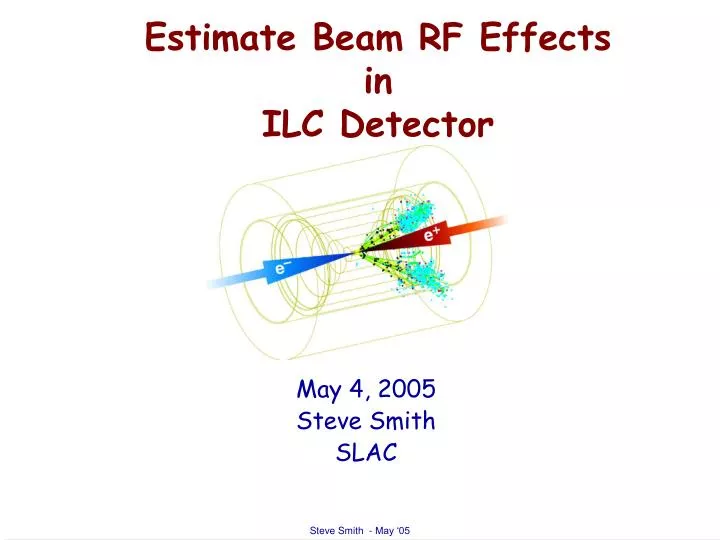
Estimate Beam RF Effects in ILC Detector. May 4, 2005 Steve Smith SLAC. Concerns. Concern about beam RF field in detector Do Beam-induced fields interfere with detector? Can we explain SLD Vertex detector problem by beam-related fields?. Approach. What can we calculate? Beam fields

E N D
Estimate Beam RF EffectsinILC Detector May 4, 2005 Steve Smith SLAC
Concerns • Concern about beam RF field in detector • Do Beam-induced fields interfere with detector? • Can we explain SLD Vertex detector problem by beam-related fields?
Approach • What can we calculate? • Beam fields • Propagation • Leakage • Coupling • Shielding • Need design • or at least design rules • What can we measure? • To what is detector sensitive? • What else makes EMI? • Self-generated noise? • Drift chamber noise? • Other beam related noise?
Sensitivity • To what is detector sensitive? • Radiated/conducted noise sensitivity • NASA requires tests, specifies protocol • Also specifies limits on emitted noise
What is Field of Beam? • Field of relativistic beam • High field due to short bunch length • But at low frequencies, all that matters is • Impulse: • Just like any other 3 nC charge on any wire.
Beam Pipe Attenuation Fields are attenuated in conductor like where “Skin effect” For 250 mm Be:
Electric Potential Outside Beam Pipe • Be pipe, 250 mm wall • Q = 3 nC • Point charge (sz =0) • Simplification: • Calculate RF shielding as planar, not pipe • I suspect real geometry (cylindrical) gives better shielding
Compare ILC and PEP • Bunch charge is comparable to PEP-II • Bunch length ~ 300 microns for ILC vs 1 cm for PEP • Shorter bunch implies more total RF power per unit charge • But extra power is beyond the PEP-II bunch length ~6 GHz • Outside the pipe you can’t see the high frequencies.
Shielding Conclusions • For zero bunch length • Q = 3 nC • 250 micron wall Be pipe • Predict: • Peak outside pipe potential F < 1 V • E < 10 V/m • Rise time ~ 200 nS • At 250 microns, a Be pipe is a good enough conductor that, outside the pipe one can't tell the difference between a femtosecond bunch and a nanosecond bunch, the high-frequency attenuation is excellent. • Inside the pipe there's a big difference!!!
Leakage Through Ports • RF can leak through ports on the beam pipe, if unshielded • Laser ports • Vacuum pump port • Gap monitor • Toroid • BPM • Bellows (150 micron Stainless much thinner than Be, much worse s ) • All can be shielded. • Should be shielded! • Ports for BPMs, diagnostics, vacuum, etc. must be connected to something via shielded cables. BPMs and other high frequency instrumentation must use decent RF cable (i.e. good shielding) to function, mostly to keep your radiated signals out of our wake field measurements! • Vacuum, optical ports, etc. might be a source of RF if an RF-screening requirement isn't put on ALL systems.
Cable Leakage Power leakage from 1’ of cable to power in the coax as a function of frequency from www.timesmicrowave.com
Cable-Cable Leakage • Try to measure coupling between 2 double–braid cables • According to previous slide measurement is hopeless • Layout • Double braid RG-223 • common in instrumentation world • Solid wall coax said to be better • Lay two lengths of cable together for 1 m. • Terminate one end of each • Drive one at +10 dBm at 2 GHz, 3 GHz • Receive on the other • Spectrum analyzer can resolve coupling to -120 dBm • No indication of coupling, upper limit of -130 dB • Repeat with RG-223 to RG-58 (single braid) • Can see ~-101 dB coupling in 1 m
Are Calculated fields large? Compare to other electric fields likely to be present • Digital clock signals • If electronics are sensitive to ~ 1 MHz, external beam seen through Be pipe is similar to fields of 1 V clock on a single-ended 50 W line (unshielded) • Vertex detector preamps (Wave hands wildly here) • Current draw during charge collection mcuh higher than charge collected from diode • Correlated with beam • Co-located with sensitive parts • Drift chamber RF signal strength
Compare to SLD Drift Chamber Clean event: • Hadronic multiplicity ~30 • Track length ~ 1m • ~30 to 50 ion pairs/cm • Gas gain ~ 105. • Charge ~ 1 nC • Across 3 kV gap • Amounts to ~ half of the 3 nC in beam charge. • Broader spectrum, extends to ~ GHz • Noisy process, random avalanches • Essentially no shielding from drift chamber RF
SLD Drift Chamber Noise Blasts Noisy pulses in SLD limited running conditions • Trip levels set to ~ 5 mA • Single noisy pulse often tripped. • IF not tripping, THEN turn up the luminosity! • Guard wires isolated by 1 M, 1 mF • Change in current of 5 mA in a pulse • => 5 mC charge in gas avalanche, per layer • Signal spectrum extends to ~ GHz. • Essentially no shielding to VXD • Compare to 3 nC in beam charge.
Electronics Near Beam Ducts Example: • PEP-II BPMs • Electronics in tunnel under dipoles. • Note that hear we are directly coupling out beam fields into low-noise electronics • Sensitive to microvolt signals coupled directly up low-loss cable. • Our signals ARE the beam fields • Our pickups are in the pipe because the signal doesn’t get out • We understand these signals quantitatively, in magnitude, spectrum, and propagation.
Other Beam-Related Effects Radiation • PEP BPMs in tunnel • Processor memory frequently corrupted. • Highly correlated to local beam losses as measured by residual radiation. • Fix: • Add shielding • reduce nearby beam losses • continuously perform memory checks • reboot as needed.
Conclusions • Measure susceptibility of electronics • Ref: NASA testing protocol • Measure emitted EMI • (so your emitted noise doesn’t plague the rest of us!) • Pay attention to good RF practice • Your system and your neighbors! • Shield bellows • Inside or outside pipe or both • Shield ports, vacuum pump HV • Leave no electrical feedthrough unconnected. • Require well-shielded cable, even for systems which don’t need them for their own performance. • In principle can bring vacuum pump HV in on a single wire • And the pump still works • But it’s a bad idea!