Download
1 / 4
40 likes | 45 Views
GIC Manufactures a variety of Industrial Electronic Timer Switches, Synchronous Timers, Cyclic Timers, Digital Timers, digital timer switches, Programmable Timer Switches and programmable timers at an affordable cost.

E N D
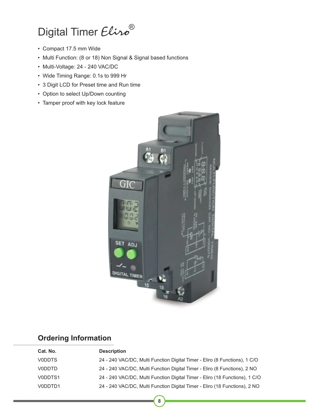
® Digital Timer • Compact 17.5 mm Wide • Multi Function: (8 or 18) Non Signal & Signal based functions • Multi-Voltage: 24 - 240 VAC/DC • Wide Timing Range: 0.1s to 999 Hr • 3 Digit LCD for Preset time and Run time • Option to select Up/Down counting • Tamper proof with key lock feature Ordering Information Cat. No. Description V0DDTS 24 - 240 VAC/DC, Multi Function Digital Timer - Eliro (8 Functions), 1 C/O V0DDTD 24 - 240 VAC/DC, Multi Function Digital Timer - Eliro (8 Functions), 2 NO V0DDTS1 24 - 240 VAC/DC, Multi Function Digital Timer - Eliro (18 Functions), 1 C/O V0DDTD1 24 - 240 VAC/DC, Multi Function Digital Timer - Eliro (18 Functions), 2 NO 8
® Digital Timer V0DDTS V0DDTS1 Cat. No. V0DDTD V0DDTD1 Parameters Timer Description Multi Function Digital Timer Functions 1) 2) 3) 4) 5) 6) 7) 8) 9) 10) Signal OFF Delay 11) Impulse ON/OFF 12) Signal OFF/ON 13) Leading Edge Impulse 1 14) Leading Edge Impulse 2 15) Trailing Edge Impulse 1 16) Trailing Edge Impulse 2 17) Delayed Impulse 18) Inverted Signal ON Delay ON Delay Cyclic OFF/ON Cyclic ON/OFF Impulse on Energizing Accumulative Delay on Signal Accumulative Delay on Inverted Signal Accumulative Impulse on Signal Signal ON Delay Inverted Signal ON Delay 1) ON Delay 2) Cyclic OFF/ON 3) Cyclic ON/OFF 4) Signal ON/OFF 5) Signal OFF Delay 6) Interval 7) Signal OFF/ON 8) One Shot Output Supply Voltage ( ) 24 - 240 VAC/DC -15% to +10% 50/60 Hz 0.5 VA (@ 24/48 VAC), 4 VA (@ 110 to 265 VAC/DC) 0.1s to 999h Supply Variation (of ) Frequency Power Consumption (Max.) Timing Range Reset Time Repeat Accuracy Relay Output Contact Rating Electrical Life Mechanical Life 200 ms (Max.) ± 0.5% 2 NO 2 NO 1 C/O 1 C/O 8A @ 240 VAC / 24 VDC (Resistive) Output 5 1x10 2x10 7 Rated Voltage (Ue): 125/240 V, Rated Current (Ie): 3/1.5 A Rated Voltage (Ue): 125/250 V, Rated Current (Ie): 2/0.22/0.1 A AC - 15 DC - 13 Utilization Category -1 ° C o + 5° C 0 -2 ° C o + 5° C 5 9 % 0 t 5 t 6 (R h) Operating Temperature Storage Temperature Humidity (Non Condensing) Re LE elay ON d D R LED Indication Enclosure Dimension (W x H x D) (in mm) Weight (unpacked) Approx. Mounting F ame Retarda t U l 18 X 5 8 X 6 85 g DIN Rail n L9 4-V0 7 Certification RoHS Compliant Degree of Protection IP 20 f r o Termin ls, IP a 30 f r o Encl osu re, P 0 o F nt I 4 f r ro sid e EMI / EMC Harmonic Current Emissions ESD Radiated Susceptibility Electrical Fast Transients Surges Conducted Susceptibility Voltage Dips & Interruptions (AC) IEC 61000-4-11 Voltage Dips & Interruptions (DC) IEC 61000-4-29 Conducted Emission Radiated Emission IEC 61000-3-2 IEC 61000-4-2 IEC 61000-4-3 IEC 61000-4-4 IEC 61000-4-5 IEC 61000-4-6 CISPR 14-1 CISPR 14-1 Environmental Cold Heat Dry Heat Vibration Repetitive Shock Non-Repetitive Shock IEC 60068-2-1 IEC 60068-2-2 IEC 60068-2-6 IEC 60068-2-27 IEC 60068-2-27 9
® Digital Timer FUNCTIONAL DIAGRAMS FOR V0DDTS & V0DDTD : Supply Voltage, S: Input Signal, R: Relay Output T: Preset Time, TON: Preset ON Time, TOFF: Preset OFF Time ON DELAY (A) On application of supply voltage, the preset time duration (T) starts. On completion of the preset time, the output is switched ON and remains ON till the supply voltage is present S R T CYCLIC OFF/ON {OFF Start, (Sym, Asym)} (b) On application of supply voltage, the output is initially switched OFF for the preset ‘OFF’ time duration (TOFF) after which it is switched ON for the preset ‘ON’ time duration (TON). This cycle repeats and continues till the supply is present. S R TOFF TOFF TON TON CYCLIC ON/OFF {ON Start, (Sym, Asym)} (C) On application of supply voltage, the output is initially switched ON for the preset ‘ON’ time duration (TON) after which it is switched OFF for the preset ‘OFF’ time duration (TOFF). This cycle repeats and continues till the supply is present. S R TOFF TOFF TON TON SIGNAL ON/OFF (d) The output relay is turned ON for Preset Time (T) whenever the Signal(S) is applied or removed. S R T T T T SIGNAL OFF DELAY (E) On application of supply voltage and input signal, the output is switched ON. When the signal is removed the preset time duration commences & the output is switched OFF at the end of the time duration. S R T INTERVAL (F) When supply power is applied to the timer and on application of input signal the output is immediately switched ON. The output remains ON for the preset time duration (T) after which it is switched OFF. S R T SIGNAL OFF / ON (G) When Signal (S) is applied or removed, the relay changes its state after Timer Duration (T) S R T T T T ONE SHOT OUTPUT (H) When Signal (S) is applied, the Timer Duration (T) starts. At the end of Timer duration (T), the relay gets energized for approximately 1 sec.(Refer Note : 2) S R T Note: 1. For Power-On operation, connect the terminal B1 to A1 permanently. 2. If the Signal (S) changes during the Timer Duration (T), it does not change the output relay but re-triggering takes places and the Timer Duration is extended. 10
® Digital Timer : Supply Voltage, S: Input Signal, R: Relay Output FUNCTIONAL DIAGRAMS FOR V0DDTS1 & V0DDTD1 T: Preset Time, TON: Preset ON Time, TOFF: Preset OFF Time ON DELAY [0] SIGNAL OFF DELAY [9] On application of supply voltage and input signal, the output is switched ON. When the signal is removed the preset time duration commences & the output is switched OFF at the end of the time duration. On application of supply voltage, the preset time duration (T) starts. On completion of the preset time, the output is switched ON and remains ON till the supply voltage is present. R S T T R T T CYCLIC OFF/ON {OFF Start, (Sym, Asym)} [1] IMPULSE ON/OFF [A] On application or removal of input signal, the output is switched ON & the preset time duration (T) starts. On completion of the time duration the output is switched OFF. When timing commences, changing the state of the input signal resets the time. R S TOFF TOFF On application of supply voltage, the output is initially switched OFF for the preset ‘OFF’ time duration (TOFF) after which it is switched ON for the preset ‘ON’ time duration (TON). This cycle repeats and continues till the supply is present. TON TON R T T T CYCLIC ON/OFF {ON start, (Sym, Asym)} [2] SIGNAL OFF/ON [b] On application of input signal, the preset delay time period (T) starts. On completion of the preset time, the output is switched ON. On removal of input signal, the preset time period starts again and the output is switched ON when the preset time duration is complete. R S TOFF TOFF On application of supply voltage, the output is initially switched ON for the preset ‘ON’ time duration (TON) after which it is switched OFF for the preset ‘OFF’ time duration (TOFF). This cycle repeats and continues till the supply is present. TON TON R T T IMPULSE ON ENERGIZING [3] LEADING EDGE IMPULSE1 [C] On application of supply voltage, the output is instantly switched ON for the preset time duration (T) after which it is switched OFF. On application of input signal the output is immediately switched ON. The output remains ON for the preset time duration (T) after which it is switched OFF. If the input signal is removed during the preset time, the output remains unaffected. R S T T R T T T ACCUMULATIVE DELAY ON SIGNAL [4] LEADING EDGE IMPULSE2 [d] On application of input signal the output is immediately switched ON. The output remains ON for the preset time duration (T) after which it is switched OFF. If the input signal is removed during the preset time, the output is immediately switched OFF. S S On application of supply voltage, the preset timing duration commences. When input signal is applied, the timing pauses and resumes only when the input signal is removed. The output is switched ON at the end of the preset time duration (T). t1 t2 R R T+t1+t2 T T ACCUMULATIVE DELAY ON INVERTED SIGNAL [5] TRAILING EDGE IMPULSE1 [E] When the input signal to the timer is removed, the output is immediately switched ON for the preset time duration (T) after which it is switched OFF. If the input signal is applied during the preset time, the output is immediately switched OFF. S S t2 t1 On application of supply voltage and input signal, the preset timing duration commences. When the signal is removed the timing pauses and resumes when the signal is applied. The output is switched ON at the end of the preset time duration (T). R R T+t1+t2 T T ACCUMULATIVE IMPULSE ON SIGNAL [6] TRAILING EDGE IMPULSE2 [F] When the input signal to the timer is removed, the output is immediately switched ON for the preset time duration (T) after which it is switched OFF. If the input signal is applied during the preset time, the output remains unaffected. S S On application of supply voltage the output is switched ON & the preset timing duration commences. When the signal is applied the timing pauses and resumes when the signal is removed. The output is switched OFF at the end of the preset time duration (T). t1 t2 R R T+t1+t2 T T T DELAYED IMPULSE [G] SIGNAL ON DELAY [7] On application of input signal, the preset time duration (T) starts. On completion of the preset time, the output is switched ON and remains ON till the input signal is present On application of input signal, the preset ‘OFF’ time duration (TOFF) starts. the output is switched ON at the end of the preset ‘OFF’ time duration & the preset ‘ON’ time duration commences irrespective of signal level and remains ON till the completion of ‘TON’. S S R R T TOFF TON INVERTED SIGNAL ON DELAY [8] INVERTED SIGNAL ON DELAY-TYPE 2 [H] On application of supply voltage, the preset time duration (T) starts. When input signal is applied, the timing pauses & resumes only when the signal is removed. On completion of the preset time, the output is switched ON. S S Timing starts only upon signal ‘S’ transition high to low. During timing or after completion of Time (i.e. relay on), any signal transition is ignored. To reset the timer supply has to be interrupted. R R T T 11