Download
1 / 26
650 likes | 1.8k Views
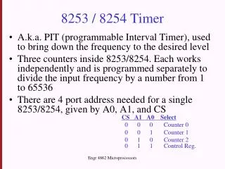
8254 Programmable Interval Timer. Dr A Sahu Dept of Comp Sc & Engg . IIT Guwahati. Hierarchy of I/O Control Devices. 2 Port (A,B), No Bidirectional HS mode (C) 4 mode timer. 8155 I/O + Timer. 8255 I/O. 2 Port (A,B) A is Bidirectional HS mode (C) Extra controls. 8253/54 Timer.

E N D
8254 Programmable Interval Timer Dr A Sahu Dept of Comp Sc & Engg. IIT Guwahati
Hierarchy of I/O Control Devices 2 Port (A,B), No Bidirectional HS mode (C) 4 mode timer 8155 I/O + Timer 8255 I/O 2 Port (A,B) A is Bidirectional HS mode (C) Extra controls 8253/54 Timer 6 mode timer 8259 Interrupt controller 8237 DMA controller 8251 Serial I/O USART controller
Outline • Basic Difference of 8155 I/O timer Vs 8254 • 8254 Brief • Architecture of 8254 • Control register • Status register • Modes of Counters with example • Read-Back modes
8155: Timer Modes Output CLK WR • 00: Single square wave of wavelength TC/2 (TC/2,TC/2 if TC even; [TC+1/2],[TC-1/2] if TC odd) • 01: Square waves of wavelength TC (TC/2,TC/2 if TC even; [TC+1/2],[TC-1/2] if TC odd) • 10: Single pulse on the TC'th clock pulse • 11: Single pulse on every TC'th clock pulse. Mode 00 N/2 N/2 Mode 01 N/2 N/2 N/2 N/2 Mode 10 N Mode 11 N N
8254: Brief • Three independent 16-bit programmable counters (timers). • It generates accurate time delays and can be used for • Real time clock, an event Ctr, a digital one shot, a square wave gen, complex wave gen. • Programmable and work DC to 8 MHz • 5 different modes of operation
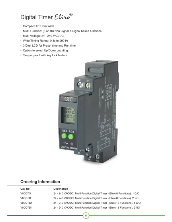
The 8254 PIT • The 8254 Programmable Interval-timer is used by the PC system for (1) generating timer-tick interrupts (rate is 18.2 per sec), (2) performing dynamic memory-refresh (reads ram once every 15 microseconds), and (3) generates ‘beeps’ of PC speaker • When the speaker-function isn’t needed, the 8254 is available for other purposes
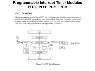
8254 Block Diagram Internal Bus D0-D7 Data Bus Buffer Counter 0 CLK 0 GATE 0 OUT 0 RDb WRb A0 A1 CSb Read/ Write Logic Counter 1 CLK 1 GATE 1 OUT 1 Counter 2 CLK 2 GATE 2 OUT 2 Control Word Register
Control Logic • RDb, WRb, CSb • A0, A1: Selection of Counter and Control Register • Suppose Address is (80H,81H,82H,83H) with interfacing Circuit
Programming Counters • Each counter may be programmed with a count of 1 to FFFFH. • Minimum count is 1 all modes except 2 and 3 with minimum count of 2. • Each counter has a program control word used to select the way the counter operates. • If two bytes are programmed, then the first byte (LSB) stops the count, and the second byte (MSB) starts the counter with the new count.
Modes of 8254 Counter • Mode 0 : Interrupt on Terminal count • Mode 1 : Hardware Retriggerable One Shot • Mode 2 : Rate Generator • Mode 3 : Square wave generator • Mode 4 : Software Triggered Strobe • Mode 5 : Hardware Triggered Strobe
Mode 0: Interrupt on Terminal Count • The output becomes a logic 0 when the control word is written and remains there until N plus the number of programmed counts. CLK OUT Count of 7 loaded
Mode 1: Hardware Retriggerable One Shot • The G input triggers the counter to output a 0 pulse for `count' clocks. • Counter reloaded if G is pulsed again. CLK GATE OUT Triggered with count of 5
Mode 2: Rate Generator • Counter generates a series of pulses 1 clock pulse wide. • The separation between pulses is determined by the count. • The cycle is repeated until reprogrammed or G pin set to 0. CLK OUT Count of 5 loaded
Write instruction to generate pulse every 50mcroS from Ctr0 • Control word = 14H • D7D6=00 Select ctr 0 • D5D4=01 load 8 bit count • D3D2D1=010 mode 2 • D0=0 Binary • Count = 50x10-6/0.5x10-6=64H PULSE: MVI A 14H ; Control word OUT CTRAdd 83H MVI A,64H ;Count value OUT 80H ; load counter 0 with low order byte HALT
Mode 3: Square wave generator • Generates a continuous square-wave with G set to 1. • If count is even, 50% duty cycle otherwise OUT is high 1 cycle longer CLK OUT Count of 6 loaded
Write instruction for 1KhZ square wave at Ctr 1 • Control word = 76H • Count= 1x10⁻³/0.5x10-6=2000=07D0H • Instructions MVI A,76H ; load Control word for Ctr 1 mode 3 OUT 83H ; write to Ctrl reg MVI A, D0H; lower order byte cnt OUT 81H MVI A,07H ; higher order byte OUT 81H HLT
Mode 4: Software Triggered Strobe • Software triggered one-shot (G must be 1). • OUT goes initially High, it goes low for one clock at the end of count • The count must be reloaded for subsequent output CLK OUT Triggered with count of 8
Mode 5: Hardware Triggered Strobe • Hardware triggered is one-shot • It is triggered by rising edge at the Gate • Initially the OUT is low and Gate triggered from low to high the count begins • OUT goes low for one clock periood CLK OUT H/W trigger with count of 8
Read-Back Command • This allow user to read the count and status of the counter • Command Written in control register and count of the specified counter can be latched • Control word 11 01 011 0 (D6H) in control word will latch the count of CNT0 & CNT1
Read-Back Command • Status can be read if STATUSb bit D4 =0 • D7=1 : Outpin is 1, 0 Outpin is 0 • D6=1: Null count, D6: 0= Count available for reading • D5-D0:Counter Programmed mode
Write a SR to generate an interrupt every 1 Second • Assume Clock Freq=2MhZ • Count is too large • Counter 1 load with 50,000 to generate 25ms • CNTLOAD=50,00010=C350H • Counter 2 load with 40 to generate 25msX40=-1S pulse (CNTLOAD=4010=28H) • Counter1 input is to counter 2 • Both Counter 1 & Counter 2 in Mode 2
Control word • Counter 1 (74H) • Counter 2 (94H)
Instruction to set up 1s interrupt MVI A , 74H ; Mode for 1st CTR OUT 83H ;Write in control register MVI A,94H ; Mode for 2nd CTR OUT 83H ; Write to control register MVI A,50 ; low byte of CTR1=C350 OUT 81H ; load to CTR1 low byte MVI A,C3 ; high byte of CTR1=C350 OUT 81H ; load to CTR1 high byte MVI A,28H ; Count for Counter 2 OUT 82H ; Load Counter 2 RET