Download
1 / 56
560 likes | 567 Views
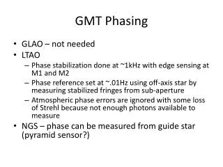
GMT-X4 is a DIN rail-mounted weighing transmitter with four-channel. When one of the four channels' load cells is damaged, GMT-X4 will automatically identify and give an alarm by displaying the alarm message on the screen. It has the characteristics of compact design, stable performance, and easy operation, which can be used for various weighing applications, such as weight checking, loss-in-weight, liquid filling, batching, vessel and silo weighing, etc.<br><br>

E N D
GMT-X4 User’s Manual 110611040002 VER01.00.01
Copyright © Shenzhen General Measure Technology Co., Ltd. All RightsReserved. Without the permission of Shenzhen General Measure Technology Co., Ltd. no unit or individual shall copy, transmit, transcribe or translate into other languages in any form or by any means. The transmitter uses DC24V power supply, use AC220V power will cause permanent damage to the transmitter. Please keep the transmitter well grounded. Warning The transmitter is electrostatic sensitive equipment, please pay attention to take anti-static measures in the use and maintenance Product Standard:GB/T 7724—2008 Verification Regulation:JJG 669-2016 Standard & Certification CMC Accuracy Class 3(6000e) ; Guangdong system 0000000048; Safety Certificate:CE
Content 1. General Description.........................................................................................................- 1 - 1.1 Functions and Characteristics................................................................................- 1 - 1.2 Technical Specifications........................................................................................- 1 - 2. Panels and buttons...........................................................................................................- 3 - 2.1 Front Panel Description.........................................................................................- 3 - 2.2 Key specification...................................................................................................- 3 - 3 Installation and Wiring.....................................................................................................- 6 - 3.1 Connection of Power Supply.................................................................................- 6 - 3.2 Connection of Load Cell.......................................................................................- 6 - 3.3 Connection of I/O Terminal.................................................................................. - 7 - 3.4 Serial port connection............................................................................................- 8 - 3.4.1 Serial port fault troubleshooting.................................................................- 8 - 3.5 CAN connect.........................................................................................................- 8 - 3.6 NetCom Connection..............................................................................................- 9 - 3.6.1 Troubleshooting Network Port Faults........................................................- 9 - 3.7Analog connection.................................................................................................- 9 - 4 Menu Review..................................................................................................................- 11 - 4.1 PARAtransmitter option and setting....................................................................- 11 - 5. Basic PARAtransmitter.................................................................................................- 13 - 5.1 Content.................................................................................................................- 13 - 5.2 Zero Cfg...............................................................................................................- 14 - 5.3 Tare function........................................................................................................- 14 - 6 Calibration......................................................................................................................- 16 - 6.1 Weight Format.....................................................................................................- 16 - 6.2 CAL Zero.............................................................................................................- 17 - 6.3 CAL Weight.........................................................................................................- 17 - 6.4 Theory CAL.........................................................................................................- 18 - 7Application setting..........................................................................................................- 20 - 7.1 Input Cfg..............................................................................................................- 20 - 7.2 Output Cfg...........................................................................................................- 21 - 7.3 COMP Config......................................................................................................- 22 - 7.4 Application Example...........................................................................................- 22 - 8Analog Parameter........................................................................................................... - 24 - 8.1Analog parameter description..............................................................................- 24 - 8.2Analog calibration............................................................................................... - 24 - 9. Communication............................................................................................................. - 25 - 9.1 Communication PARA transmitters....................................................................- 25 - 10. Maintenance.................................................................................................................- 27 - 10.1 IO Test...............................................................................................................- 27 -
10.2 Serial Port Test...................................................................................................- 28 - 10.2.1.................................................................................................................- 28 - 10.2.2.................................................................................................................- 28 - 11. Communication protocol and address.........................................................................- 29 - 11.1 Modbus protocol...............................................................................................- 29 - 11.1.1 Function code and and exception code description............................... - 29 - 11.1.2 Communication Mode............................................................................- 29 - 11.1.3 Modbus communication data sheet........................................................- 30 - 11.2 GM-Cont...........................................................................................................- 30 - 11.3 CAN OPEN Protocol.........................................................................................- 31 - 11.3.1 Standard frame active report data format...............................................- 31 - 11.3.2 Standard frame read data format............................................................- 32 - 11.3.3 Standard frame write in data format.......................................................- 33 - 11.3.3 The extended frame actively reports the data format.............................- 34 - 11.4 PROFINET COMM........................................................................................- 34 - 11.4.1 IO state....................................................................................................- 35 - 11.4.2 Device description file GSD.................................................................. - 37 - 11.5 EtherCAT communication.................................................................................- 37 - 11.5.1 Simplified parameter address.................................................................- 38 - 11.5.2 Device description file ESI.................................................................... - 40 - 11. DIMENSION...............................................................................................................- 41 - Appendix 1........................................................................................................................ - 42 - Modbus communication data sheet...................................................................- 42 -
GMT-X4 user’s manual 1. General Description 1.1 Functions and Characteristics DIN Rail mounted, stainless steel housing 4 way 6 wire analog load cell weighing platform interface, connection 10 350 Ω load cells at most 160*128 1.96”white light OLED Support Chinese,English Shell type load cell interface Display Language Preset point function 8 - way com PARA tor 5 comparison options Load cell interface 1 way RS485 interface 1 way RS232 interface 4 way 6 line analog load cell scale interface,40*350Ω load cell maximum connect Support modbus RTU and connect methord 4 interface,each channel 1 in 2 out,low level valid 1 way CAN OPEN Bus interface,support CAN communication 4 way analog input output interface(Current/voltage) Signal network port, support TCP/IP Profinet Bus interface Ethernet/IP Bus interface EtherCAT Bus interface in 8 out transistor input output IO interface Interface Option 1 Option 2 Option 3 1.2 Technical Specifications Power supply 24VDC(18~36VDC) Dimension GW Certified working environment Working environment Storage environment Power Load cell excitation voltage Load cell requirements Input sensitivity 62*134*127.5(mm) 883g -10~ ~ 40℃ ; 90%R.H without dew ℃; -20~ ~ 60℃ ; 90%R.H without dew ℃; -40~ 20W ~ 60℃ ; 90%R.H without dew ℃; 5V 200Ma(MAX) 4 simulated Load cell, connect 40 350 Ω load cells, most support 1 mv/V, 2 mv/V, 3 mv/V sensitivity 0.1Uv/d - 1 -
GMT-X4 user’s manual Input range Non-linerarity A/D conversion speed Display Precision Keyboard Decimal Places Overload 0.00~ 0.01% F.S ~ 15mV(load cell 3mV/V) 50;60;100;120;200;240;400;480;800;960(SPS) 1/1000000 6 key sound keyboard 0, 0.0, 0.00, 0.000, 0.0000;5 options OFL - 2 -
GMT-X4 user’s manual 2. Panels and buttons 2.1 Front Panel Description Status: Power: COM1 : indicator blinks during data communication COM2 : : Communication indicator. After the RS232 connection is successful, the indicator blinks during data communication NET : :Communication indicator. This indicator blinks during network port communication or bus communication. CAN: Communication indicator: blinks when CAN communicate. lights up when indicator is power on : Communication indicator. After the RS485 connection is successful, the 2.2 Key specification GMT-X4 has 6 button functions, short press and long press have differences, button diagram is shown as below: K Key ey I Interface nterface S Short hort press press L Long ong press press Weight/analog display Quickly view the voltage values of load cell in channels 1 to 4 Main - 3 -
GMT-X4 user’s manual Menu interface Data input Option select page Previous Sub PARAtransmitter Data +1 Previous Sub PARAtransmitter Channel /clear tare Next Sub PARAtransmitter Data or letter-1 Next Sub PARAtransmitter Check channel 1~4 tare value Next Sub PARAtransmitter Input position move to left / Switch Capital / 1~4 tare Channel 1~4 gross/net mode shift: gross/net mode Main Menu interface Data input Menu interface / / / Channel 1~4 quick set tare,set tare value Main Menu interface / Data input / Option select / / Channel 1 ~ 4 quick check the zero voltage Main / / Menu interface Next Sub PARAtransmitter Input position move to right / Data input / Option select / / Quickly view the front and back software versions and compilation dates Main Menu page Menu interface Data input Option select Comfirm Selection / Comfirm Selection Comfirm Selection / / Quick channel 1~4 zeroing (gross mode valid) Return to previous level Fast Calibrate Zero(If Gross), N/A(if Net) Main Menu interface / - 4 -
GMT-X4 user’s manual Data input Option select Exit Back to Weight Display page / / - 5 -
GMT-X4 user’s manual 3 Installation and Wiring 3.1 Connection of Power Supply GMT-X4 weighing transmitter connects with DC24V power supply as follows: :The transmitter uses DC24V power supply, use NOTE: AC220V power will cause permanent damage to the transmitter. 3.2 Connection of Load Cell GMT-X4 weighing transmitter connects with bridge type resistance strain gauge load cells. :(Note:n=1,2,3,4) PORTS EXn+ SNn+ EXn- SNn- SIGn+ SIGn- SHL 6 wires EX+ SN+ EX- SN- SIG+ SIG- SHL 4 wires EX+ EX- SIG+ SIG- SHL ※When connected to a 4-wire load cell, the EXn+ and SNn+ ports, EXn- and SNn- ports must be short-connected.Otherwise, the transmitter weight data reading is not normal. NOTE: 1. As the output signal of the load cell is an analog signal sensitive to electronic noise, shielded cables should be used for load cell wiring and laid se PARA tely from other cables, especially away from ac power supply 2. For the occasions with short transmission distance and little temperature change or low accuracy requirements, four-wire load cell can be selected.However, for applications requiring high transmission distance or accuracy, a six-wire load cell should be selected. 3. For the application of multi-load cell PARAllel connection, the sensitivity (mV/V) of : - 6 -
GMT-X4 user’s manual each load cell should be consistent. 3.3 Connection of I/O Terminal GMT-X4 weighing transmitter I/O module is an optional interface function,need to declare before order, 4 IN 8 OUT,Standard IO input, output connector factory default low level is valid.Adopt transistor output mode, each drive current 200mA. Option 1 Input disgram: Low level mode Output disgram: Low level mode The default definition is as follows: Output Input OUT1 OUT2 OUT3 OUT4 OUT5 OUT6 OUT7 OUT8 NONE NONE NONE NONE NONE NONE NONE NONE IN1 IN2 IN3 IN4 NONE NONE NONE NONE - 7 -
GMT-X4 user’s manual 3.4 Serial port connection GMT-X4 :1 way RS485, 1 way RS232 COM RS232 connection mode: RS485 connection mode: ※ GND is ground of RS485, it can very much improve communication quality via connecting with GND by low-resistance wire when there is a lot of disturbance in working field. ※ GND must be connected in RS232 mode 3.4.1 Serial port fault troubleshooting If serial port can’t communicate, please check: ○ Refer 3.5 to check line, make sure connection is corrct. RS232 must connect 3 lines, Rx, RS485 must connect line A, B ○ Make sure connecting port COM ID, baud rate, data format and communication protocol must consistent with the computer and PLC. , Tx, , GND PARAtransmitters are the same to computer. 3.5 CAN connect Support 1 way CAN communicate interface, can communicate with computer. GMT-X4 module can connect to bus network as a slave station module, badu rate support 100K, ,125K,250K, ,500K, ,1000K. Conntect to CAN bus network,connect methord refer to below charts,note bus network terminal need to add adaptive resistance. - 8 -
GMT-X4 user’s manual 3.6 NetCom Connection GMT-X4 support NetCom communication and PN, Ethernet CAT bus communication mode (optional fuction,make statement when order) .Support TCPprotocol and Profinet, Ethernet CAT bus protocol. 1) When choose Netcom, support TCP protocol; LAN 1 can communicate, LAN2 disabled temporarily 2) Ethernet CAT communication, LAN2 as the entrance, and more than one device connection, between the devices to serial connection, distinguish the entrance and exit order. 3.6.1 Troubleshooting Network Port Faults If Network can’t communicate, please check: ○ Check Network indicator light Hardware connection is normal, the communiation light inside is ON. The network cable is connected and the connection indicator blinks ○ Check whether the communication protocols is consistent with the host computer and PLC. ○ Verify that GMT-X4 can be pinged from the network, if not, check the hareware interface section. ○ Check whether IP address conflicts exist ○ Restart transmitter 3.7Analog connection GMT-X4 has analog output function (optional fuction,make statement when order) , can equipped with 4 analog output function. Each channel corresponds to one analog output function. Interface is as follows: V-IOUTx+(+) 、V-IOUTx-(-) (Note:x=1~4,means 4 channels) - 9 -
GMT-X4 user’s manual Analog output is divided into voltage output type and current output type, support 0~5V, 0~10V, 4~20mA, 0~20mA, 0~24mA. User can select the corresponding mode in the output mode of analog quantity paremeter. Analog communication mode, calibrate please refer to 8 - 10 -
GMT-X4 user’s manual 4 Menu Review 4.1 PARAtransmitter option and setting PARAtransmitter option:(Select tare operation switch PARAtransmitter) - 11 -
GMT-X4 user’s manual PARAtransmitter Setting:(Set the power reset range from 49% to 30%) ※ After setting completed,press ENT key,pop out”operation success”. ※ When setting, press ESC key, exits current PARAtransmitter entry. ※ Refer to the 2nd chapter to the specific meaning of the key 【key function】 - 12 -
GMT-X4 user’s manual 5. Basic PARAtransmitter 5.1 Content PARAtransmitter 1. Zero Cfg DefaultValue Decription PARAtransmitters Set CH1~4 Zero Range:0~101(✕full range %); 0: : turn off PWR-On Zero; 1-100: full range 1-100% zeroing; 101: last zero before turn OFF After set ON, the zeroing operation can be carried out through the communication port.If set to OFF, the communication port can not be reset. Range:1~99(✕full range %) Set CH1~4 tare cfg Range:OFF: :can’t communication to tare; ON: :can communication to tare Range:OFF ;ON: :Reset after power off, still maintant previous tare value. Range: Disable; CorrectTare; BackToGross Range:0~full range, write tare value. Set CH1~4 STAB TrZero PARAtransmitters Range:0-99,When the is 0, turn off the STAB function and the weight STAB marker is always in effect.When the PARAtransmitter is not 0, the weight is stable if the weight variation range is not greater than the set fractional read during the stability determination time Range:1-5000 Milliseconds.If the weight range does not exceed the STAB range during that time, the weight is stable Range 0-99d.Turn off the zero tracking function when the PARAtransmitter is 0.When the PARAtransmitter is not zero, the weight change is less than the range of zero tracking time, the system will automatically : according : reset to 1.1 PWR-On Zero 0 1.2 Remote Zero ON 1.3 Zero Range 2. Tare Cfg 20% PARAtransmitters 2.1 Remote Tare ON 2.2 Tare Record OFF 2.3 NetSign COR 2.4 Preset Tare OFF 0 3. STAB&TrZero PARAtransmitter 3.1 STAB Range 1d 3.2 STAB Timer 1000ms 3.3 TrZero Range 1d - 13 -
GMT-X4 user’s manual track zero. Range 1-5000ms, during the tracking time, if the weight change is less than the tracking range, the system will automatically track the zero position Set CH1~4 filter PARAtransmitters Range:0-9;The larger the number is, the higher the filtering intensity will be, but the response time will be longer. Range 0-99d,At 0, the steady-state filter is turned off.When the non-zero, if the weight change is within the range, then the steady-state filter is started Range: 50; 60; 100; 120; 200; 240; 400; 480;800;960(SPS) Set CH1~4 signal range Range:0-5mV;0-10mV;0-15mV Transmitter according input range to adjust signal sampling range to make sure more specific 3.4 TrZero Time 1000ms 4. FIR&Sample 4.1 Digit-Filter 4 PARAtransmitter is 4.2Adv. Filter 00 4.3 AD Sample 200 Rate 5. Load cell signal 0-10mV 5.1-5.4 CH1-4 6. Basic PARAtransmitter reset Reset factory defaults to each Channel PARAtransmitters 6.1~6.4 reset CH1-4 // 5.2 Zero Cfg Zero success condition: 1) Weighing platform stabe;2)Weight is in zero range. Zero Cfg: 1) Press Zero;2)Zero input port is valid;3) communicate port zero(1.2 Remote Zero is ON) 5.3 Tare function Tare operation ON/OFF: ON/OFF serial port with IO tare;This set to ON for tare setting operation. Tare Record: ON/FORBIT Tare Record function. If turn ON, power off restart, retain tare weight. NetSign COR: OFF: NetSign have no operation. - 14 -
GMT-X4 user’s manual Correct Tare:When transmitter in net weight status, the net weight is negative and weight is stable, then indicator will correct tare value to ensure Net weight is not negative. Back to Tare: When transmitter in net weight status, the net weight is negative and weight is stable, then indicator will back to gross weight status Preset Tare: Set tare weight, if the value is not 0, then this tare weight is used for tare. ※NOTE: The transmitter is in tare state, when clear tare, transmitter record GW, enter NW mode. The transmitter can’t be reset in the mode of NW display. - 15 -
GMT-X4 user’s manual 6 Calibration When GMX-T4 weight transmitter or any part of the weighing system is changed for the first time and the current equipment calibration PARA transmitters can’t meet the user’s requirements, the display shall be calibrated. Calibration can determine the system zero and gain of the weighing system. 6.1 Weight Format Initial Value Decription PARAtransmitter 1. Weight Format 1.1 Unit 1.2 Decimal 1.3 Division 3.1 Calibration 1 Range:t;kg;g;lb Range:0;0.0;0.00;0.000;0.0000 Range:1, 2, 5, 10, 20, 50 The maximum value of the transmitter is generally taken as the range of the load cell. x 200000 Configurable. When the Range is over (" data over Range "), a message is displayed to prevent the weighing overvoltage from damaging the load cell. CH1~4 CALZero operation After emptying the scale, press the "OK" button and set the current state to zero。 Manually and manually input the voltage of 4 decimal points as the zero point voltage CH1~4 CALWeight operation Weight CP 1 Calibrate weight points, support 5-point calibration. When the front point is calibrated, the other weight points will be reset to the uncalibrated state (the default value is 10.0000mV, 10000kg). If the marking point 1 is performed, the marking point 2-5 is reset to 0 CH1~4 Theory CAL True load cell sensitivity, 4 decimal points, average sensitivity if multiple load cells The true load cell range, if there are more than one load cell, is the sum of all load cell ranges Enable calibration of theoretical values and make them effective. Range: OFF; ON. CH1~4 CALCorrect kg 0 1 Range: Division 1.4 Full Scale 10000 2. CAL Zero 2.1Auto Capture 2.2 Key In mV 3. CALWeight Weight CP 2 Weight CP 3 Weight CP 4 3.1~3.4 CH1-4 Weight CP 5 4. Theory CAL 4.1 LC mV/V 2.0000 4.2 LC Capacity 10000 4.3 Use T-CAL OFF 5. CAL Correct - 16 -
GMT-X4 user’s manual After calibration, if the zero point is correct, the weight has deviation, which can be used to correct the weight value.The value calculation: if the transmitter weight isA, but the weight after weighing is B, the correction coefficient is calculated: (actual weight ✕ current correction coefficient)/B showsA weight 5.1 Correct Coef 1.00000 6. CAL Reset The calibration PARA transmitters of each channel are restored to factory Settings, and the reset is successful by pressing the [ENT] confirm key. 6.1~6.4 reset CH 1-4 // 6.2 CAL Zero Zero calibration is the zero calibration of the scale. Zero calibration can be done in two ways: automatic acquisition and manual input.The “Auto Capture “method must be used for zero calibration when new equipment or weighing structure is adjusted Auto Auto Capture Capture: Calibration conditions: stable scale Transmitter displays current millivolt. After empty the scale, press ENT to calibrate the current state to zero. Load cell voltage 0.6688mV Key Key In In mV mV: User need key in voltage value of ZERO point to calibrate ZERO 222 Key In mV 00.0000mV ※Generally used for no-weight calibration, the value recorded by the data recorded during the calibration of the weights is used for Key In mV. 6.3 CALWeight Cal weight is to use standard weights for weight calibration. Supports 5-point calibration, providing users with the maximum ability to select calibration points according to their needs. Calibration method (take CH 1 for example): ※ Zero calibration should be completed before weight calibration CAL Weight 3.1CH1 - 17 -
GMT-X4 user’s manual Press ENT Load weights onto the weighing table CH1 CAL Weight Weight CP 1 2.3267mV Press ENT Enter the weight value corresponding to the weight Weight CP 1 Weight Cal OK Weight CP 1 000100 Multi-point calibration attention: 1) User can choose the number of marking points, such as single point calibration, which can be withdrawn after the first weight point is calibrated 2) Cross-point calibration is not allowed. For example, when using 3-point calibration, it is necessary to calibrate the Weight CP1, 2 and 3, but it is not possible to calibrate the Weight CP3 and 4 by crossing the Weight CP2 after the completion of the Weight CP1 3) In the multi-point calibration, the weight should be increased. For example, the weight of Weight CP2 must be heavier than the weight of Weight CP1 6.4 Theory CAL Calibration of theory value means that weight calibration is performed by inputting load cell sensitivity and load cell range value Theory CAL takes 3 steps: 1) Set load cell sensitivity (If multiple load cell are connected, input the mean value) 2) Set total range of the load cell (If connected to more than one load cell, input total range) 3) Turn on "Use T-CAL" key. - 18 -
GMT-X4 user’s manual - 19 -
GMT-X4 user’s manual 7Application setting 7.1 Input Cfg Enter port configuration PARAtransmitters in the transmitter application PARA transmitter item. The transmitter is equipped with 4 input interfaces and 8 output interfaces, which can meet the function of 4 in and 8 out I/O. The application function of input port 1~4 and the shaking time can be set se PARA tely. The initial default function is not available, and the customer can define it by himself. PARA PARAtransmitter transmitter Item Item Specification Specification PARAtransmitter PARAtransmitter Range:NONE,CH1~4 ZERO,CH1~4 CAL-ZERO,CH1~4 TARE,CH1~4 CLEAR-TARE,CH1~4 GROSS/NET,COMP-ON; ※It is defined as nonfunctional that is, the input port is nonfunctional Avoid misjudgment caused by signal jitter. Initial Value:5ms;Range:0-200ms Input 1~4 function Input Config Input 1~4 Delay Time Input fuction description: Function NONE CH1~4 ZERO CH1~4 CAL-ZERO CH1~4 TARE CH1~4 CLEAR TARE CH1~4 GROSS/NET Description / When this signal is valid, start zeroing This signal is valid and (273) hardware protect ON/OFF turn to OFF, starts CAL ZERO This signal is valid, starts tare This signal is valid, starts clear tare, means recover clear tare weight This signal input is valid, starts NET/GROSS shift. This function is defined. The output of the comparison point is controlled by the state of the I/O port.If the comparison condition is COMP-ON - 20 -
GMT-X4 user’s manual valid and the input is valid, the com PARAtor output will be valid; otherwise, it will not be output. If this function is not defined, the comparison condition holds and there will be output, which is not controlled by the input port. Example: :Define Input2 as TARE ※ enter input port, press to switch to the corresponding input define function. ※ output port function defined in the same way 7.2 Output Cfg Output port configuration PARA transmitters apply to the transmitter PARA transmitter item. The functions of outlet 1-8 can be set. The initial default is no function, but the customer can define it by himself PARA PARA transmitter transmitter Item Item Range: NONE,COMP 1-8,CH1~4 STAB,CH1~4 ZERO, CH1~4 NET, CH1~4 -SIGN; ※Define no function means Output no function PARA PARA Specification Specification transmitter transmitter Output Config Output 1-8 function Output function description Function No function COMP 1-8 Description No output Com PARAtor 1-8 has output when conditions are met; port is set to enable the comparison point, the input is valid and the com PARAtor has an output Transmitter stab signal output is valid Transmitter zero indicate light valid output is valid When transmitter is in net weight, output is valid When display weight less than 0, output is valid If the input CH1~4 STAB CH1~4 ZERO CH1~4 NET CH1~4-SIGN - 21 -
GMT-X4 user’s manual 7.3 COMP Config In the com PARAtor configuration PARAtransmitter, can set the comparison channel 1~8, comparison mode, comparison condition, ON COND. and OFF COND. GMT-X4 provides 8 com PARAtors, 341x—348x Specification PARAtransmitter PARAtransmitter Which channel is compared in independent mode: 0- CH 1, 1- CH 2, 2- CH weight/flow judgment: OFF, ≤(weight) , =(weight) , ≠(weight) , ≥(weight) , <>(weight) , ≮≯(weight) ; ※If current weight is NET, the weight is NET, if current weight is gross weight, the weight is gross weight. Higher priority comparison value. When there is only one comparison PARAtransmitter, this comparison value is used by default.Initial value: 0; Range: -999999-999999. (Press the up and down arrow to switch between positive and negative signs) When two comparison values are used, the value must be greater than the first comparison value. Initial value: 0; Range: -999999-999999 ( Press the up and down arrow to switch between positive and negative signs) When the comparison is successful, the transmitter outputs additional constraints that are valid。Initial value:Immediately; Option:1, Immediately(Output immediately as long as the comparison condition holds) ;2, Stable(Output is provided when the comparison condition is valid and the current weight is stable) ; 3,Debounce (The output is displayed after the success time exceeds the decision time) COMP CH 3, 3- CH 4.default:0 COMP Mode COMP Value-1 COMP Value-2 ON COND. TRUE JudgeT Initial value:1000ms;Range:0~50000ms An additional restriction that invalidates the transmitter output when the comparison changes from success to failure;Initial value: Immediately; Option: Immediately,Stable,Debounce (The failure time becomes invalid after the failure time exceeds the FALSE HoldT) OFF COND. FALSE HoldT Initial value:1000ms;Range:0~50000ms 7.4Application Example Example 1:When the weight is greater than or equal to 500g, the output 1 is valid; when the weight is not satisfied and the weight is stable, the output 1 is invalid. Setup:1)Output Config Output -1 Set to:COMP 1 2)The comparison mode is set to:≥(weight) - 22 -
GMT-X4 user’s manual 3)The comparison value 1 is set to:500 4 ) The comparison value 2 is set to 0 : 0 ( single point comparison, this PARAtransmitter is invalid) 5)ON COND. is set to:Output after weight STAB 6)TRUE JudgeT:0(in non-delay mode, this PARAtransmitter is invalid) 7)OFF COND.is set to:Invalid after weight STAB 8)FALSE HoldT:0(in non-delay mode, this PARA transmitter is invalid) ※If the weight is ≥ 500g, the steady state remains invalid, then output 1 does not switch to the valid state. Example 2:The weight is ≮≯ 200g, 500g, after delay 5ms output 4 is valid,if the condition is not met,output 4 is invalid after 5mS delay. Setup:1)Output Config Output -4 Set to:COMP 1 2)The comparison mode is set to:≮≯(weight) 3)The comparison value 1 is set to:200 4)The comparison value 2 is set to:500(this value should be greater than 1) 5)ON COND.is set to:Delay output 6)TRUE JudgeT:5ms 7)OFF COND. Is set to:Delay output 8)FALSE HoldT:5ms - 23 -
GMT-X4 user’s manual 8Analog Parameter GMT-X4 provides four analog output channels. Each channel provides one analog output channel. For details about analog port connections, see Chapter 3.7. parameters corresponding to CH 1 to 4 are as follows: The analog 8.1Analog parameter description Parameter 1.Analog output mode 2. Analog associated variable 3.Analog mA CAL 4.Analog Volt CAL 5.Analog PARA reset Initial value 4-20mA range:4-20mA, 0-20mA, 0-24mA, 0-5V, 0-10V Current weight range:Current weight, NW, GW. Analog correspond to the weight form Detail operation refer to 8.2 analog calibration current analog para reset to factory setting value / 8.2Analog calibration Analog Output mode can choose current/voltage. In the normal display state, you can press to view the analog output values of the four channels. The format is X. XXmA/V. The output of analog quantity has been calibrated before delivery, so the user does not need to calibrate the output of analog quantity. abnormal, the user can calibrate the analog quantity by himself. calibration methods are the same. Here, the current calibration of CH1 is taken as an example (it is recommended to calibrate under the guidance of professionals): If the output of analog quantity is The current and voltage - 24 -
GMT-X4 user’s manual 9. Communication GMT-X4 has various communication function interfaces : COM-1 ( RS485 ) COM-2(RS232), Ethernet-IP, (support TCP, PN bus functions) ), 9.1 Communication PARAtransmitters Initial value Specification COM-1/2 parameter Range:01-99 Range:4800, 9600, 19200, 38400, 57600, 115200 Range:Modbus RTU, GM-Cont. Range:8-N-1,8-E-1,8-O-1,7-E-1, 7-O-1 Note:Modbus only support 8 data bits Range:AB-CD(Hi_low) , CD-AB(Low_Hi) Under continuous transmission protocol, the time interval between frames. Range 0-5000ms, default value:20ms CAN OPEN parameter Range:1-127 Range:100K, 125K, 250K, 500K, 1000K Option:standard frame, Extended frame COM ID 01 Baudrate 38400 Protocol Modbus RTU Data Format 8-E-1 Dword Format AB-CD Send Gap 20ms CAN COM ID Baudrate Report frame format Report frame content Report Gap 01 250K Extended frame Option:weight, Volt Weight 20ms Range:0-5000ms TCP-IP parameter Range:000.000.000.000-255.255.255.255 Range:000.000.000.000-255.255.255.255 IP Config Subnet mask Communication gateway 192.168.000. 101 255. 255. 255. 000 Range:000.000.000.000-255.255.255.255 192.168.000. 001 Socket No. Range : 1-65535, set the network communication socket No.,0 close the connection Standard network can set,Range include:protocol include:Modbus/TCP, GM-Cont/TCP Range: AB CD, CDAB; ; Standard network can set, Hi-Lo byte mode, when protocol is Modbus/TCP use When protocol is GM-Cont, this parameter is used 502 Protocol Modbus/TCP Connect1 Dword Format AB CD Send 20ms - 25 -
GMT-X4 user’s manual Gap for send gap time. Range:0-5000ms Connect 2~connect 6 Socket No. defaule value is 0, other parameter refer connect 1’s communicate parameter Profinet 192.168.000.101 Range: :0.0.0.0~255.255.255.255 Range:OFF, ON; (When choose PN attached plate,this parameter can see) ON: PN communicate, transmitter parameter is control by main site“module parameter”, when transmitter power on main site“module parameter” setting parameter auto write in. OFF:PN communicate, transmitter parameter not control by main site”module parameter” Floating point weight weight, floating weight, floating volt EtherCAT Option: OFF, ON. When turn on non cyclical parameter can write in 0 Range:0-65535 Communicate parameter reset This parameter is used to restore communication parameters to factory settings. Enter this parameter when resetting communication parameters. CAL/RST PWD, default:000000. Can revise PWD in this way【Maintenance】--【PWD Protect】--【CAL/RST PWD】 IP Config Write Switch OFF PLC display type choose switch. Range:intergral Data type Write Switch OFF Site alias - 26 -
GMT-X4 user’s manual 10. Maintenance 10.1 IO Test IO The test function is used to test whether the connection state of the input/output outlet is normal. Input test: ※Enter 1 to test OK, press the key to switch the input port for testing ※After the test is complete, press ESC to exit and enter the test status - 27 -
GMT-X4 user’s manual Output test: ※Under the test state of the output port, press ENT to switch the external output state.※ External state can be converted with ENT key switch, indicating that the output port is normally connected. 10.2 Serial Port Test Serial port test function, in a fixed baud rate (9600), data format (8-N-1) to send and receive data, to detect the serial port connection status. 10.2.1 Receive test:The external sends test data (ASCII code only) to the transmitter and displays the data on the display. The data length of each frame cannot exceed 10 bytes. If the external sends 30 31 41 to the transmitter and the transmitter displays as shown in the figure below, then the COM-485 connection is normal. COM-232 is the same methord 10.2.2 Send Test:Send data"COMx Test nnn". If is COM-485 then X=1, if is COM-232 then X=2 - 28 -
GMT-X4 user’s manual 11. Communication protocol and address 11.1 Modbus protocol 11.1.1 Function code and and exception code description Function code Functio n code Item Specification 03 06 Read register Write a single register Amaximum of 125 registers can be read at a time This transmitter command only supports writing to the double register. When writing, the address must be aligned. It is not allowed to write only part of the double register. Write multiple registers 16 01 05 Read the coil Write the coil Note that this length is in bits. Note: Only supports above Modbus function codes. When sending other function codes the transmitter will not respond. Exception Code Respond Code Item 02 Illegal data address not allowed. 03 Illegal data value 04 Computer attempting to perform the requested operation. 07 Unsuccessful programming request Specification This error code indicates that the data address received is The data written is not in the allowed range. An unrecoverable error occurred while the transmitter was For the transmitter, the command received cannot be executed under the current conditions. 11.1.2 Communication Mode RTU When communicating in RTU mode, every 8 bits (1 byte) in the data is divided into two 4-bit hexadecimal characters Mark the end of a frame with an interval of more than 3.5 characters. more reliable end, you are advised to use an interval of at least 4.0 characters The specific protocol is as follows: : Supported data format: 8-bit data bit, 1-bit stop bit, parity check (8-E-1) 8 data bits, 1 stop bit, odd check (8-O-1) 8 data bits, 1 stop bit, no checksum (8-n-1) Code: Binary ( (1) ) ( (2) For a ) - 29 -
GMT-X4 user’s manual 11.1.3 Modbus communication data sheet For details, refer to Appendix 1 11.2 GM-Cont GMT-X4 when COM Protocol is“GM-Cont”,send data according below format. CH1 CH2 Scale No. value CH1 Data Format 2 byte 1 byte 1 byte 6 byte Among: CH3 CH4 STX state1 state2 weight CRC CR LF Each take up 8 byte, refer 02H 2byte 0D 0A Scale No.——2 byte, display current scale No., Range:01~99; state1—— ——1 byte, format as below: bit7 bit6 bit5 bit4 bit3 bit2 bit1 bit0 g 0 0 0 0 0 0 Kg 0 1 0.0 0 0 1 t 1 0 0.00 0 1 0 Fix 0 Lb 1 1 0.000 0 1 1 0.0000 1 0 0 Weight Unit Decimal state2—— bit7 ——1byte, format as below: bit6 bit5 bit4 bit3 bit2 bit1 bit0 Reserve Reserve Reserve GROSS/NET 0-GROSS 1-NET +/- 0-+ 1-- ZERO 0-None ZERO 1-ZERO STAB 0-Un Stable 1- STAB overflow 0-normal 1- overflow Fix 0 Fix 1 Fix 0 CH2,CH3,CH4—— weight value—— is positive (negative) overflow.; ——Data Format and CH1 are same,details please refer to CH1; ——6 byte no direct data;Returns "blank space OFL space" when weight CRC——2 byte,Cal and All the values in front of the check bits are added up and converted to decimal data, and then the last two bits are converted to ASCII (tens before, ones after) For example For example below frame data: (02 30 31 00 41 20 20 20 37 30 30 09 51 20 20 20 32 30 30 12 4B 20 20 33 30 30 30 1B 4C 20 20 4F 46 4C 20) 31 39 0D 0A The sum of 02~20:5EF(Hex) , converted to decimal as 1519. It can be calculated that the check codes of this data frame are 31 and 39. Example: The current transmitter automatically returns data:02 30 31 00 41 20 20 20 37 30 30 09 51 20 20 20 32 30 30 12 4B 20 20 33 30 30 30 1B 4C 20 20 4F 46 4C 20 31 39 0D 0A - 30 -
GMT-X4 user’s manual The current transmitter state is stable: CH1 in gross weight,STAB state, the weight value is positive, and the current weight value is 700g, , CH2 is NET,STAB state, weight value is +,currentweight value is 20.0kg, CH3 is gross weight, STAB state, weight value is -,currentweight value is-30.00t, CH4 is-OFL state, display OFL. 11.3 CAN OPEN Protocol 1)Support 100K, 125K, 250K, 500K, 1000K bus speed, can set in the "CAN OPEN" parameter of communication parameters. 2) There are two different frame formats, mainly the length of the identifier field is different, with 11 bit identifier (ID) is the standard frame, and with 29 bit identifier is the extended frame. The frame format is detailed in the following table: 11.3.1 Standard frame active report data format bit10 bit9 bit8 bit7 bit6 bit5 bit4 bit3 bit2 bit1 bit0 address Local device address(1~127) 11bits frame ID Frame function 10: voltage :active report weight; ;11 active report reserved( (fix 0) ) Data format Byte7 Byte6 Byte5 Byte4 Word 3 32 bit integer signed number , OFL,-OFL display weight data is 9999999, -9999999 ,data Hi-Lo, , weight data Word 2 Below status valid is 1 D7: :ADC Fault D6: :Load cell short circuit D5: :load cell OFL D4: :weight OFL D3: :effective theoretical value D2: :display NW D1: :stable D0: :ZERO current data frame channel No.(0-3) Byte3 channel status Word 1 Byte2 Byte1 Byte0 channel No. Word 0 reserved fix 0 - 31 -
GMT-X4 user’s manual 11.3.2 Standard frame read data format bit10 bit9 bit8 bit7 bit6 bit5 bit4 bit3 bit2 address Target device address 11bits frame ID Frame function frame direction Data type Fix 01: :read parameter Fix 0: :from host to COM ID bit1 bit0 0: :word(2byte); Data format ;1: :Dword(4byte) Byte7 Byte6 Byte5 Byte4 Byte3 Byte2 Byte1 Byte0 Word 3 0 Word 2 0 Word 1 0 Word 0 read address Read back to result data format bit10 bit9 bit8 bit7 bit6 bit5 bit4 bit3 bit2 address local device address (1~127) 11bits frame ID Frame function frame direction data type Fix 01: :read parameter Fix 0: :from host to COM ID bit1 bit0 0: :word (2byte); Back to data format ;1: :Dword(4byte) Byte7 Byte6 Byte5 Byte4 Byte3 Byte2 Byte1 Word 3 read Dword Lo word CD part or read word Word 2 Read Dword Hi word AB part Back to data Operation result: unconscionable :0 OK, , 1 address error, , 2 data Word 1 Word 0 read address Byte0 - 32 -
GMT-X4 user’s manual 11.3.3 Standard frame write in data format bit10 bit9 bit8 bit7 bit6 bit5 bit4 bit3 bit2 address target device address 11bits frame ID Frame function frame direction data type Fix 00: : parameter write in Fix 0: : from Host to COM ID bit1 bit0 0: :Word(2byte); Data ;1: :Dword(4byte) Byte7 Byte6 Byte5 Byte4 Byte3 Byte2 Byte1 Byte0 Word 3 write in Dword Lo-word CD or word content Word 2 write in Dword Hi word AB write in parameter contents Word 1 0 Word 0 write in address Write in back to result data format bit10 bit9 bit8 bit7 bit6 bit5 bit4 bit3 bit2 address local device address (1~127) 11bits frame ID frame function frame direction data type Fix 00: :parameter write in Fix 1: : From COM ID to Host bit1 bit0 0: :word (2byte); Back to data format ;1: :Dword(4byte) Byte7 Byte6 Word 3 write in Dword CD or word content Byte5 Word 2 write in Dword AB Byte4 Byte3 Operative result: 0 sucess, ,1 address error , : Word 1 ,2 data unresonable Byte2 Byte1 Word 0 Write in address Byte0 - 33 -
GMT-X4 user’s manual 11.3.3 The extended frame actively reports the data format bit28 bit27 bit26 bit25 bit24 bit23 bit22 bit21 bit20 address local device address (1~127) frame function frame direction report content reserved 10: :active report weight; ;11 active report volt bit19 Fix 1: : From COM ID to Host bit18 bit17 bit16 bit15 bit14 bit13 bit12 bit11 bit10 bit9 bit8 bit7 bit6 bit5 bit4 bit3 bit2 bit1 bit0 00: 01: Fix 0 :report data( :report data( (CH 1, (CH 3, ,2) ,4) ) ) below state valid is 1 bit15: :ADC error bit14: :load cell short circuit bit13: :load cell OFL bit12: :weight OFL bit11: :theory valid bit10: :display NW bit9: :stable bit8: :zero 29 bits frame ID CH(1,3) data state below state valid is 1 bit7: :ADC error bit6: :load cell short circuit bit5: :load cell OFL bit4: :weight OFL bit3: :theory valid bit2: :display NW bit1: :stable bit0: :zero CH(2,4) data state Data Byte7 Byte6 Byte5 Byte4 Byte3 Byte2 Byte1 Byte0 Word 0 CH (1,3) weight data The returned data is a hexadecimal number, a 32-bit integer signed number, data Hi-Lo. When OFL and –OFL, the weight data is 9999999 and -9999999. If it is a voltage value, the voltage value has 3 decimal places by default Word 1 Word 2 CH (2,4) weight data Word 3 11.4 PROFINET COMM GMT-X4 display has two PROFINET-IO bus connect port:LAN1 and LAN2, can - 34 -
GMT-X4 user’s manual connect to the PROFINET bus as a Profinet-IO slave station.. Transmitter IP address please check at【COMM PARA】--【Profinet】 please check at【Maintenance】--【system info】. 】 ;MAC address 11.4.1 IO state GMT-X4 provides 36 byte IO, the master station can read and control the status of the weighing display. 10.7.1.1 PN cyclic PARA IO module address Deviation Deviation PARA PARA D Data ata type type PARA PARA Specification Specification weight and state PARA( (read register, CH1 Currently displayed weight integer/weight floating-point (depending on the PN parameter data type), default display floating-point weight. D15: :communication heartbeat,(After the connection is established, the value of the PN's communication heartbeat is converted between 0 and 1 at a frequency of 1 Hz) D14: :write state, (write data return state register address illegal 2: parameter error) D12-D13: reserved D11:Use theory value calculate weight,(Use theory value calculate weight prompt user) D10: ADC fault,(ADC initialization failure or sampling interruption longer than expected) D9:Net weight of the current display, (distinguish which weight is currently displayed) D8:mV STAB,(mark of million volt stability in calibration) D7:load cell-OFL, lower load cell mV allow Range , I address) ) Current Display weight/ Volt 0 DWord 0:no error 1: Weight state marker bit 4 Word D6:load cell OFL, Over load cellmV allow Range D5:weight –OFL, weight <“-( Full Scale +9d)” D4:weight OFL, weight >“ Full Scale +9d” D3:OFL state,(weight or load cell abnormal) D2:display weight -,(display weight is -) D1:ZERO,(weight is in 0+/- 1/4d Range) D0:STAB D15: calibrate state(0:normal;1: calibrate fail) D14: D13:The remote tare operation permit switch is not enabled when the tare is operated remotely D12:NETstate does not allow TARE : calibrating unstable, waiting till stable error code 1 6 Word D11: When tare, the weight is negative D10: ZERO, load cell OFL - 35 -
GMT-X4 user’s manual D09: ZERO, load cell-OFL D08: ZERO,no STAB D07:NETstate not allow ZERO D06:The remote reset switch is not turned on during remote reset D05:ZERO, load cell OFL D04:ZERO, load cell-OFL D03:ZERO,no STAB D02:ZERO over Range D01:power on.ZERO no STAB D00:power on ZERO over Range CH2 Currently displayed weight integer/weight floating-point (depending on the PN parameter data type), default display floating-point weight. Refer CH1 state byte (Note: differ with CH1, D14-D15 are reserved) Refer CH1 error code 1 CH3 Currently displayed weight integer/weight floating-point (depending on the PN parameter data type), default display floating-point weight. Refer CH1 state byte (Note: differ with CH1, D14-D15 are reserved) Refer CH1error code 1 CH4 Currently displayed weight integer/weight floating-point (depending on the PN parameter data type), default display floating-point weight. Refer CH1 state byte (Note: differ with CH1, D14-D15 are reserved) Refer CH1error code 1 The value obtained by writing the address to read (writeregister, , Q address) Current display weight 8 DWord State byte 12 Word error code 2 14 Word Current display weight 16 DWord State byte 20 Word error code 3 22 Word currentdisplay weight 24 DWord State byte 28 Word error code4 read out value function Operate and PARA modify( 30 Word 32 DWord ) D5-D7 Reserve D4: CAL ZERO 10 D3: GROSS/NET 8 D2:clear tare 4 D1:TARE 2 D0:ZERO 1 CH1 function Operate 0 Byte CH2 function Operate CH3 function Operate CH4 function Operate Refer CH1 function Operate 1 Byte 2 Byte Refer CH1 function Operate 3 Byte Refer CH1 function Operate - 36 -
GMT-X4 user’s manual write value address(Note: address change will not write in) This PARAmodify connect port module support MODBUS address range limit 200-1187 Write value(Note:only when value change will write in transmitter) Read address(Note: Can’t read DWord address,when write an odd address) This PARAmodify connect port module support MODBUS addressRange limit 200-1187 Write value address DWord 4 Write value DWord 8 Read address DWord 12 11.4.1.2 PN non cycle PARAlist Module PARAitems power on AUTO ZERO TrZero Range STAB Range ZERO Range Digit-Filter PARA Digit-Filter level Unit Decimal Point Initial value 0 PARASpecification Range:0~99(full scale percentage) 0-9d 1 1 0-99d 20% 0%-99% 4 0-9 0 0-99 g,kg,t,lb Range:0;0.0;0.00;0.000;0.0000 transmitter value division value Range:1, 2, 5, 10, 20, 50, 100, 200, 500 transmitter full scale,normally take load cell full scale. Range : Division*200000 settable. When over fill scale( “data over range” )prompt info,avoid weighing over pressure damage load cell. CH1~CH4 CAL and ON/OFF PARA kg 0 Division d=1 Full Scale 10000 11.4.2 Device description file GSD The device description file and connection method of GMT-X4 can be downloaded from the website of Shenzhen General Measure Technology Co., Ltd. (www.gmweighing.com). 11.5 EtherCAT communication The GMT-X4 display has two bus connection ports: LAN1 and LAN2, with LAN2 serving as the entry when EtherCAT is connected. Any computer with a network interface card and any embedded device with Ethernet control can serve as a master station for EtherCAT, such as devices such as Huichuan PLC. It is also possible to connect to the transmitter through Twincat software on a PC computer, in any case within the same LAN as the transmitter. The following parameter table can be used after the connection is successful. - 37 -
GMT-X4 user’s manual 11.5.1 Simplified parameter address EtherCAT cycle parameter list Data type Parameter Description Parameter write address, D5-D7:reserved D4: calibrate Zero D3: GS/NT D2: CLEAR TARE D1:TARE D0:ZERO address of value to write(Note if address change “value to write” is written to the changed address) This PARA modify connect port module support MODBUS address range limit 200-1187 ,write only CH1~CH4 function operate (each CH takes 8 byte) UDint address of value to write UDINT value to write(Note that if the value changes, the value is written to the address of the transmitter corresponding to the value to be written) address to read(Note can’t write a word address when reading Dword address) This PARA modify connect port module support MODBUS address range limit 200-1187 PARAread address, read only current display weight, floating point type D15:communication heartbeat, (After the connection is established, the value of the PN's communication heartbeat is converted between 0 and 1 at a frequency of 1 Hz) D14:write state, (write data return state 0:no error 1: PARAerror) D12-D13:reserved D11:Calculate the weight using theoretical values, (Prompt the user when calculating weight using theoretical values) D10:ADC fault,(ADC initialization failed or sampling interrupted longer than expected) D9: current display NW, (Distinguish which weight is currently displayed) D8:mV STAB,(Millivolt stability marker during calibration) D7: load cell -OFL, lower load cell volt allow range D6:load cell OFL,over load cell volt allow range D5:Weight -OFL,weight lower“-(full range+9d)” D4:Weight OFL,weight over“full range+9d” D3:OFL state, (weight or load cell fault) D2:display weight-, (display weight-) D1:ZERO, (weight within 0+/-quarter d range) value to write UDINT address to read UDINT CH1 weight REAL CH1 weight state byte UINT - 38 -
GMT-X4 user’s manual D0:STAB D15: calibrate state(0: normal;1: calibrate fail) D14:When calibrate is unstable, waiting stable D13:When remote operate TARE, remote TARE operate allow ON/OFF is off D12:When in NW state, do not allow TARE D11: Weight is negative when TARE D10: Load cell OFL when TARE D9: Load cell -OFL when TARE D8: Unstable when TARE D7:NW stable do not allow ZERO D6:Remote ZERO remote ZERO ON/OFF is off D5:Load cell OFL when ZERO D4:Load cell -OFL when ZERO D3:Non Stable when ZERO D2:ZERO over range D1:Non Stable when PWR-On Zero D0:Over Zero Range CH1 error code UINT CH 2 weight CH 2 weight state byte CH 2 error code CH 3 weight CH 3 weight state byte CH 3 error code CH 4 weight CH 4 weight state byte CH 4 error code read out value REAL Refer above CH1 parameter read address description UINT UINT REAL Refer above CH1 parameter read address description UINT UINT REAL Refer above CH1 parameter read address description UINT UINT DINT The value obtained by the address to be read EtherCAT Non Acyclic Parameter List Module Parameter Power on Auto ZERO TrZero Range STAB Range Zero Range Digit-Filter parameter Adv. Filter Initial value Parameter description Range:0~99(✕ full range %); 0 1 0-99d CH1 calibrate and ON/OFF parameter 1 20% 0-99d 1%-99% 4 0-9 0 0-99 Unit kg g, kg, t, lb - 39 -
GMT-X4 user’s manual Decimal Point 0 Range:0;0.0;0.00;0.000;0.0000 Transmitter display value minimum value variation Range:1,2,5,10,20,50,100,200, 500 Transmitter maximum display value, normally takes load cell full range. Range: Division*200000, set over range (“data over range”) prompt message, avoid damage to the load cell by weighing overpressure. Division d=1 Full range 10000 CH2 calibrate and ON/OFF parameter CH3 calibrate and ON/OFF parameter CH4 calibrate and ON/OFF parameter Refer to the acyclic parameter of CH1 Refer to the acyclic parameter of CH1 Refer to the acyclic parameter of CH1 11.5.2 Device description file ESI GMT-X4 device description file and connection methord can download at Shenzhen General Measure Technology Co., Ltd.’s website (www.gmweighing.com) - 40 -
GMT-X4 user’s manual 11. DIMENSION - 41 -
GMT-X4 user’s manual Appendix 1 Modbus communication data sheet Display Address PLCAddress Specification Specification Weight status information CH1 current display weight value (4-byte signed integer number) CH2 current display weight value (4-byte signed integer number) CH3 current display weight value (4-byte signed integer number) CH4 current display weight value (4-byte signed integer number) byte D15 PARAtransmitters 40001-40002 40003-40004 40005-40006 40007-40008 0000-0001 0002-0003 0004-0005 0006-0007 Specification Reserved Load cell power short circuit(EXn+EXn- short circuit) D14 D12-D 13 ※ Indicates the weight status. When it is the current state, the status bit displays "1". If the current weight is zero and stable, then the address D0D1 status bit is "1" Reserved Weight is calculated using theoretical values ADC breakdown Current display NW Million volts stable Load cell -overflow Load cell +overflow Weight -overflow Weight +overflow Overflow state display weight - Zero stable D11 CH1 weight status signal byte D10 D9 D8 D7 D6 D5 D4 D3 D2 D1 D0 40009 0008 CH2 weight status signal byte CH3 weight status signal byte CH4 weight status signal byte CH1gross weight value( 4 bytes The number of signed integers) CH1 net weight value( 4 bytes The number of signed integers) CH1 tare value( 4 bytes The number of signed integers) CH2 gross weight value( 4 bytes The number of signed integers) CH2 net weight value( 4 bytes The number of signed integers) CH2 tare value( 4 bytes The number of signed integers) CH3 gross weight value( 4 bytes The number of signed integers) CH3 net weight value( 4 bytes The number of signed integers) CH3 tare value( 4 bytes The number of signed integers) CH4 gross weight value( 4 bytes The number of signed integers) CH4 net weight value( 4 bytes The number of signed integers) CH4 tare value( 4 bytes The number of signed integers) CH1 display weight value(floating-point type) CH1 gross weight value( 4-byte signed floating point number) CH1 net weight value( 4-byte signed floating point number) CH1 tare value( 4-byte signed floating point number) CH2 display weight value(floating-point type) 40010 0009 Details please refer CH1 weight status signal byte. 40011 0010 Details please refer CH1 weight status signal byte. 40012 0011 Details please refer CH1 weight status signal byte. 40013-40014 40015-40016 40017-40018 40019-40020 40021-40022 40023-40024 40025-40026 40027-40028 40029-40030 40031-40032 40033-40034 40035-40036 40037-40038 40039-40040 40041-40042 40043-40044 40045-40046 0012-0013 0014-0015 0016-0017 0018-0019 0020-0021 0022-0023 0024-0025 0026-0027 0028-0029 0030-0031 0032-0033 0034-0035 0036-0037 0038-0039 0040-0041 0042-0043 0044-0045 - 42 -
GMT-X4 user’s manual 40047-40048 40049-40050 40051-40052 40053-40054 40055-40056 40057-40058 40059-40060 40061-40062 40063-40064 40065-40066 40067-40068 0046-0047 0048-0049 0050-0051 0052-0053 0054-0055 0056-0057 0058-0059 0060-0061 0062-0063 0064-0065 0066-0067 CH2 gross weight value( 4-byte signed floating point number) CH2 net weight value( 4-byte signed floating point number) CH2 tare value( 4-byte signed floating point number) CH3 display weight value(floating-point type) CH3 gross weight value( 4-byte signed floating point number) CH3 net weight value( 4-byte signed floating point number) CH3 tare value( 4-byte signed floating point number) CH4 display weight value(floating-point type) CH4 gross weight value( 4-byte signed floating point number) CH4 net weight value( 4-byte signed floating point number) CH4 tare value( 4-byte signed floating point number) CH1 after fliter AD internal code CH1 load cell voltage value CH1 relative zero voltage value CH2 after fliter AD internal code CH2 load cell voltage value CH2 relative zero voltage value CH3 after fliter AD internal code CH3 load cell voltage value CH3 relative zero voltage value CH4 after fliter AD internal code CH4 load cell voltage value CH4 relative zero voltage value Reserve byte D4-15 D3 D2 D1 D0 Reserve byte D8-15 D7 D6 D5 D4 D3 D2 D1 D0 D10-D 15 D9 bipolar,-direct data; polar-no direct data 40069-40070 0068-0069 40071-40072 0070-0071 direct data, integer, Four decimal point 40073-40074 0072-0073 direct data, integer, Four decimal point bipolar -direct data; polar-no direct data 40075-40076 0074-0075 40077-40078 0076-0077 direct data, integer, Four decimal point 40079-40080 0078-0079 direct data, integer, Four decimal point bipolar -direct data; polar-no direct data 40081-40082 0080-0081 40083-40084 0082-0083 direct data, integer, Four decimal point 40085-40086 0084-0085 direct data, integer, Four decimal point bipolar -direct data; polar-no direct data 40087-40088 0086-0087 40089-40090 0088-0089 direct data, integer, Four decimal point 40091-40092 0090-0091 direct data, integer, Four decimal point 40093 0092 Specification Reserve Input 4 state Input 3 state Input 2 state Input 1 state 40094 0093 Input state area 40095 0094 Specification Reserve Output 8 state Output 7 state Output 6 state Output 5 state Output 4 state Output 3 state Output 2 state Output 1 state 40096 0095 Output state area Reserve Flow state symbol byte 40097 0096 IO test state - 43 -
GMT-X4 user’s manual D8 D7 D6 D5 D4 D3 D2 D1 D0 Reserve COMP 8 ON COMP 7 ON COMP 6 ON COMP 5 ON COMP 4 ON COMP 3 ON COMP 2 ON COMP 1 ON 40098~40140 0097~0139 Reserve CH1 D14-15 D13 Reserve When CAL unSTAB,waitinging Remote calibration is performed when remote calibration is prohibited Reserve The previous weight point is not calibrated Beyond minimum resolution Weight input exceeds the maximum range weight input can’t be 0 weight CAL less than ZERO or the previous CP weight CAL load cell OFL weight CAL load cell-OFL weight CAL unSTAB ZERO CAL load cell OFL ZERO CAL load cell-OFL ZERO CAL unSTAB When calibrate fail is 1 Reserve Remote tare operation is not ON. Remote tare operation is allowed to be ON/OFF Fobid Tare Tare Err OFLWhen Tare -OFLWhen Tare Non Stable NET state not allow ZERO Remote ZERO ON/OFF is not ON for remote ZERO Loadcell Over Loadcell Under Non Stable Over Full Scale power on ZERO unSTAB power on ZERO over range STAB D12 D11 D10 D9 D8 40141 0140 error code 1 D7 D6 D5 D4 D3 D2 D1 D0 D15 D14 D13 D12 D11 D10 D9 D8 D7 40142 0141 error code 2 D6 D5 D4 D3 D2 D1 D0 40144~40155 0143~0154 Reserve CH2 40156 40157 40158~40170 0155 0156 0157~0169 error code1 error code2 Reserve Refer CH1 error code1 Refer CH1 error code2 CH3 40171 40172 0170 0171 error code 1 error code 2 Refer CH1 error code1 Refer CH1 error code2 - 44 -
GMT-X4 user’s manual 40173~40185 0172~0184 Reserve CH4 40186 40187 40188~40200 0185 0186 0187~0199 error code 1 error code 2 Reserve basic PARAzero, Refer CH1 error code1 Refer CH1 error code2 , can read / write CH1 Full scale 0%-101%, Initial value: 0 (OFF) , 0: OFF power onAUTO ZERO function 1-100:power on according full scale 1-100% Range process ZERO 101: :Recover to last ZERO before power off : Power on ZERO Range 40201 0200 Remote ZERO ON/OFF ZERORange Remote Tare Tare Record 40202 0201 Range: 0 (OFF) , 1 (ON) ; Initial value: 1 (ON) 40203 40204 40205 0202 0203 0204 Full scale 1%-99%, Initial value:20% Range: 0 (OFF) , 1 (ON) ; Initial value: 1 (ON) Range: 0 (OFF) ,1 (ON) ; Initial value: 0 (OFF) Range:0(Disable) , 1(CorrectTare) , 2 (BackToGross) ;Initial value:0(OFF) Range: 0~ full scale Initial value: 0, read out current tare Range:0-99d, Initial value:1 Range:1-5000 msec, Initial value:1000 Range:0-99d, Initial value:1 Range:1-5000 msec, Initial value:1000 Range:0-9, Initial value:4 Range:0-99d, Initial value:0 Range:0-9( 0-50;1-60;2-100;3-120;4-200; 5-240;6-400;7-480;8-800;9-960) Initial value:4-200Hz Range: 0-5 ( 0: 0-5mV; 1: 0-10mV; 2: 0-15mV,) Initial value:1(0-10mV) 40206 0205 NetSign COR ,write in tare, 40207 0206 Preset Tare 40208 40209 40210 40211 40212 40213 0207 0208 0209 0210 0211 0212 STAB Range STAB Timer TrZero Range TrZero Timer Digit-Filter Adv. Filter 40214 0213 AD Sample Rate 40215 0214 Signal Range 40216~40300 0215~0299 Reserve CH2 40301-40315 40316~40400 0300-0314 0315~0399 Refer CH1 PARAzero Reserve CH3 40401-40415 40416~40500 0400-0414 0415~0499 Refer CH1 PARAzero Reserve CH4 40501-40515 40516~40600 0500-0514 0515~0599 Refer CH1 PARAzero Reserve CALPARAzero, , can read / write CH1 Range: 0-3; 0-t,1-kg,2-g,3-lb; 1 Range:0-4;0-0, 1-0.0, 2-0.00, 3-0.000, 4-0.0000; ;Initial value :0 Range:1, 2, 5, 10, 20, 50, 100, 200, 500 Range: 0-Division*200000, Only write in1; write in1, ZERO calibrates the current state read:load cell current mV. Fixed 4byte decimal ; Initial value : 40601-40602 0600-0601 Unit 40603-40604 0602-0603 Decimal Point 40605-40606 0604-0605 Division 40607-40608 0606-0607 Full Scale ,Initial value : 10000 40609-40610 0608-0609 AUTO ZERO CAL - 45 -
GMT-X4 user’s manual point Range: 0-150000; write inmV; read current ZERO mV write in weight value CALweight point 1 write in weight value CALweight point 2 write in weight value CALweight point 3 write in weight value CALweight point 4 write in weight value CALweight point 5 Write the actual sensitivity of the load cell for the theoretical value calibration , 0.0000-3.9999, default:2.0000 Write the total range of the load cell for theoretical calibration, Range:0-999999, Write 1 to enable theoretical value calibration, write 0 to use calibration data Write the coefficient to modify the calibration, write the data integer type, the system default data write data with 5 decimal point 40611-40612 0610-0611 KEY ZERO CAL 40613-40614 0612-0613 CP1 40615-40616 0614-0615 CP2 read out CP relative mV 40617-40618 0616-0617 CP3 40619-40620 0618-0619 CP4 40621-40622 0620-0621 CP5 Range : 40623-40624 0622-0623 LC mV/V 40625-40626 0624-0625 LC Capacity , default:10000 40627-40628 0626-0627 Use T-CAL 40629-40630 0628-0629 Correct Coef 40631~40700 0630~0699 Reserve CH2 40701-40730 40731~0800 0700-0729 0730~0799 Refer CH1 CAL PARA zero Reserve CH3 40801-40830 40831~40899 0800-0829 0830~0899 Refer CH1 CAL PARA zero Reserve CH4 40901-40930 40930~41000 0900-0929 0930~0999 Refer CH1 CAL PARA zero Reserve Application zero, , read-write, , otherwise read only default:0; Indep Mode mode: PARARange:0-21, 0-NONE, 1-CH1ZERO, 2-CH2 ZERO, 3-CH3 ZERO, 4-CH4 ZERO, 5-CH1 CAL-ZERO,6-CH2 CAL-ZERO,7-CH3 CAL-ZERO , 8-CH4 CAL-ZERO , TARE , 10-CH2 TARE , 12-CH4 TARE, 13-CH1clear tare, 14-CH2clear tare, 15-CH3clear tare, 16-CH4clear tare, 17-CH1 GROSS/NET, 18-CH2 GROSS/NET, 19-CH3 GROSS/NET, 20-CH4 GROSS/NET, 21- COMP-ON combo mode: PARARange:0-6, 0-NONE, 1-ZERO, 2- CAL-ZERO, 3-TARE, 4-clear tare, 5- GROSS/NET, 6-COMP-ON PARARange:0-200ms, Initial value:5ms, Refer input1 functionSpecification Refer input1 delaySpecification Refer input1 functionSpecification Refer input1 delaySpecification 9-CH1 11-CH3 TARE , 41001-41002 1000-1001 input1 function 41003-41004 41005-41006 41007-41008 41009-41010 41011-41012 1002-1003 1004-1005 1006-1007 1008-1009 1010-1011 Input 1 delay Input 2 function Input 2 delay Input 3 function Input 3 delay - 46 -