Download
1 / 10
120 likes | 678 Views
Tolerance Analysis for Non-rotational Parts. Team: Dr. X. Han, S. Yao, C. Fei Advisor: Professor Y. Rong Sponsor: NSF & Delphi Corp. Tolerance Analysis in Production Planning. Tolerance analysis - Part of setup planning - Locating error coupled with process error

E N D
Tolerance Analysis for Non-rotational Parts Team: Dr. X. Han, S. Yao, C. Fei Advisor: Professor Y. Rong Sponsor: NSF & Delphi Corp.
Tolerance Analysis in Production Planning Tolerance analysis - Part of setup planning - Locating error coupled with process error - Intra- and inter- setups - Process verification and quality control - Integration in CAD/CAM Four steps: • Tolerance stack-up analysis • Tolerance decomposition • Machining error analysis • Tolerance assignment • In process inspection • Quality control plan In this project, the first step is studied.
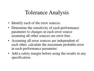
Tolerance Stack-up Analysis • Tolerance stack-up analysis is to evaluate the machining error effects in each setup on the feature tolerance specifications of the final product • Tolerance stack-up analysis • For given setup plan as DMG • For given machining errors in each operation • Evaluate the machining error accumulation through setups • Tolerance decomposition • The feature tolerances specified in product design can be decomposed into operation tolerances specified for each setup • The machining error in each setup can be decomposed into locating errors (loc) from machine tool and fixture, tool-fixture alignment errors and tool wear errors (tool), other deterministic (o) and random (ran) errors. = loc + tool + o + ran
Tolerance Achieved in One Setup • Tolerance decomposition model 1 : • Two related features are machined in one datum frame: • Tolerance decomposition model 2: • One of the features in the tolerance • relationship is the datum feature:
Tolerance Achieved in Multiple Setups • Tolerance Decomposition Model 3 The features in the tolerance relationship are machined in different setups N,N’ = N, A + A,N’ N, A = ran A,N’ = ori + ran
Tolerance Stackup Searching Algorithm In order to identify the factors that influence the machining errors, two steps are needed: • Search the datum-feature relationships that construct the tolerance stackup chain • Calculate the total machining errors Tolerance within one setup: Tolerance stackup in multi-setup:
Locating Errors Analysis Among the machine errors in one setup, the locating error (loc)can be calculated: • Six locating points(P10, P20, P30, P40, P50, P60) construct three orthogonal planes • A1 X + B1 Y + C1 Z + D1 = 0 • A2 X + B2 Y + C2 Z + D2 = 0 • A3 X + B3 Y + C3 Z + D3 = 0 • A theoretical fixturing coordinate is expressed as • X0 is the position of the origin point • is the 33 orientation matrix • Actual fixturing coordinate reflects the variation caused by locator errors • T = T0T • T = (x, y, z, , , ). T comes from the given locator errors.
An Case Study on Knuckle OP10 OP20 Machining feature GD&T of OP10: 101 Surface A Theoretical fixture CS: Actual fixture CS with given locator errors( ) The worse case caused by locator errors: 0.654 Overall machining error Total = locating + mt + process +tool = 0.654 + 0.013 + 0.254 + 0 = 0.921 mm mt,process and tool are given parameters.
A Case Study on Engine Block Datum frames:X-Y-Z, XX-YY-ZZ, A-B-C, M-S-A-R
Summary A comprehensive tolerance analysis framework is established for machining system planning and verification. Tolerance stackup analysis has been studies for non-rotational part. Three tolerance decomposition models are developed for intra- and inter-setup analysis. • An inter-setup tolerance stackup algorithm have been implemented. • The calculation of locating errors has been implemented. • The analysis is integrated in CAD/CAM Acknowledgement: Dr. Y. Zhang and Dr. W. Hu contributed to the earlier work of the project.