Download
1 / 22
230 likes | 424 Views
The Canning Crescent Centre. The Canning Crescent Centre. Presentation of the building. Building concept. Monitoring campaigns. Monitoring results. Major findings. More information. Back to “Select a building”. Nat Vent. Building presentation (1...). Building information:

E N D
The Canning Crescent Centre The Canning Crescent Centre Presentation of the building Building concept Monitoring campaigns Monitoring results Major findings More information... Back to “Select a building” NatVent
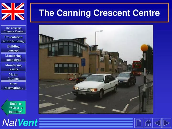
Building presentation (1...) • Building information: • Architects: MacCormac Jamieson, Prichard, UK • Building Services Engineer: Atelier One, UK • Research team monitoring the building: Dr Vina Kukadia, James Pike, Martin White, Building Research Establishment, UK • The Canning Crescent Centre is a community day-care centre completed in 1994 at a cost of £1.3 million. It is an L-shaped two-storey building with a gross floor area of 1350 m2. It is located on a busy high street in Wood Green, an urban area of London where air pollution and noise levels are high. • It is a high thermal mass construction comprising a steel frame with exposed brick walls and a concrete ground floor ceiling. • The south west side of the building faces the busy high street where air and noise pollution is high. • The north east side faces a ‘clean’ enclosed garden courtyard and car park.
Building presentation (2|) Plan view of ground and first floor The Canning Crescent Centre from the courtyard car park
Building concept (1...)Ventilation philosophy • Design of building and ventilation strategy is based on • low budget so there is no mechanical ventilation • the need to protect patient confidentiality from pedestrians in the high street overhearing conversations • the need to prevent the ingress of air pollution and noise from the high street • Diaphragm cross walls used to provide a series of individual chimneys which allow air to be drawn through the building by wind and buoyancy forces. • Fresh air for the whole building comes exclusively from the ‘clean’ courtyard side. • Window opening along the front of the building facing the high street is discouraged.
Building concept (2...)Ventilation philosophy Series of individual chimneys
Building concept (3...)Ventilation system - room facing courtyard • Air supply is purely by openable windows and trickle ventilators located in the window frames. • Air exhaust from each room is via a high level wooden extract grille and its own exhaust stack. Openable windows with trickle ventilators Air extract grille at high level Room facing the courtyard
Building concept (4...)Ventilation system - room facing courtyard Air supply and extract grille in room facing high street Fresh air intake on externalwall facing courtyard High level air extract grille Low level air supply grille • Air is supplied through openings in the external courtyard facing wall • Air is then ducted through the footings of the building to low level wooden supply grilles.
Building concept (4|)Ventilation system - Air exhaust stack Low pressure zone induced below aerofoil, drawing air up chimney (Bernoulli effect) Air flow across chimney Solar ‘accelerator’ Adjustable air flow damper • Adjustable air flowdamper in the stacks controls the air change rate in each room • Dampers in the stack are controlled manually and set centrally to • Fully open in the summer to aid cooling • Almost closed in the winter to provide reduced flow rates sufficient to maintain optimum indoor air quality and minimise energy loss Damper actuator: Air from internal spaces exits at high levels
Building concept (5|)Ventilation strategy • Winter ventilation strategy • All dampers set in an almost closed position to provide background air for ventilation and removal of carbon dioxide. • Local control of dampers allows increased rates of air flow in individual offices when required. • Summer ventilation strategy • Dampers in the stacks are set in the fully open position to maximise air flow rates to cool the thermal mass of the building. • Automatic roof lights open up to purge the heat from the building during the night time. • Solar heated double glazed panels at the top are intended to provide increased buoyancy and hence extract flow rate.
Monitoring campaign (1...) • Aims of monitoring campaign: • To determine the performance of the ventilation strategy all year round in terms of • Thermal comfort • Removal of carbon dioxide • Minimising ingress of external pollution into the building • To provide recommendations for improvement of ventilation system if necessary • Monitoring was carried out in • four offices • Two facing the high street, ground and first floor. • Two facing the courtyard, ground and first floor. • corridor • high street • seminar room
Temperature sensor Noise meter T 4 Sample tube Dosing tube T 3 A External sample point Hot-wire anemometer N Courtyard Busy High Street Seminar room Monitoring campaign (2...)Location of measurements Location of measurements Plan view
Winter monitoring Monitoring carried out over 1 week in March 1997 Air change rates Local air velocity Temperature Internal mean radiant External air Humidity Carbon dioxide Summer monitoring Monitoring carried out over 1 week in July1997 Air change rates Temperature Internal mean radiant External air Humidity Carbon dioxide Indoor Air Quality and other measurements Monitoring carried out over 1 week in March 1997 Carbon monoxide Nitrogen oxides Sulphur dioxide Noise Air flow rate through inlet grille Occupant questionnaire and interviews Monitoring campaign (3|)different campaigns
Monitoring results (1…)- winter • Results for office 3 - good representation of all monitored offices • Ventilation rates of 1 to 2 air changes per hour (ach) were obtained. Mean internal daily temperatures varied between 17-25°C. This is slightly higher than a design temperature of 18°C. • Relative humidity levels varied between 40 to 60%. • Carbon dioxide levels increased in the presence of occupants but reduced rapidly to background levels of 400 ppm in their absence. This also occurred in summer. • Local air velocities averaged at 0.1 ms-1(not shown)
Monitoring results (2...)- winter The fresh air supply is sufficient The IAQ is acceptable: the CO2-concentrations are below the limit of 1200 ppm. Tint. Text. CO2./1000 Air Change Rate The air change rate is sometimes relatively high, when the office is not occupied. This leads to unnecessary energy losses. This problem occurs because the settings of the flow dampers are not clear to the occupants.
Monitoring results (3...)- summer Results for office 3 - good representation of all monitored offices • Ventilation rates of about 2-3 ach were generally obtained; and about 17 ach when the dampers in the stack were manually opened for periods of one hour. However the night ventilation strategy was not implemented. This is mainly due to the fact that the settings of the flow dampers are not clear to the occupants. • Mean internal daily temperatures varied between 17 to 27.5°C. • The IAQ is acceptable: the CO2 -concentrations are below the limit of 1200 ppm. Monitoring results: see next slide…
Monitoring results (4...)- summer Text. CO2 ./1000 Tint. Air Change Rate
Monitoring results (5...)Indoor air quality • Carbon monoxide (CO), nitrogen oxide (NO), nitrogen dioxide (NO2) and sulphur dioxide (SO2 ) levels were well within recommended air quality guidelines
Monitoring results (6|)Occupant questionnaires • Occupants reactions were as follows: • Cold down draughts from the high level extract grilles were felt during the winter; as a result the grilles were sealed with plastic film and cardboard. • Electrical fan heaters were used as auxiliary heat sources in the winter. • During the summer there was considerable overheating in the offices facing the courtyard. Extract grille covered with card
Findings & Improvements (1...) • Issues and lessons learnt: • Summer-time comfort could be improved by a more effective intensive night ventilation, which would cool down the thermal mass. The ventilation system functions were ineffective due to several reasons: • Master stack damper control labelling was unclear and resulted in the wrong setting being applied during the summer period. • Inadequate maintenance of dampers resulted in the dampers being ‘stuck’ in the closed position even in the summer. • Dampers being leaky or ‘stuck’ in the open position resulted in cold down draughts during the winter. • High pressure losses in the stack may have contributed to reduced air change rates. • Summer-time comfort could also be improved by installing external shading devices to reduce the solar gains through the windows.
Conclusions (2...) • Suggested improvements: • Removal of air flow dampers in each exhaust stack. • Replacement of inlet and outlet openings with conventional slide control grilles. • Central damper settings should be clearly marked ‘open’ for the summer and ‘closed’ for the winter. • To prevent cold down draughts, a small low-energy priming fan is recommended. • In the design calculations all pressure drops need to be accounted for. • Conclusion: • Air intakes from the ‘clean’ garden courtyard side ensured that the ingress of external pollution and noise was minimised. • ….
Conclusions (3|) • Suggested improvements: • ... • Regular maintenance of the ventilation system and correct labelling of the dampers are required to ensure correct operation. • All controls should be readily understood and be easy to operate by maintenance staff, facilities managers and office staff. • The operation of the building can be substantially improved by introducing the modifications suggested. The BRE research team would like to express their thanks to • N Morris, M Osbourne and M Strachan from the Canning Crescent Centre, UK • I Logan from MacCormac, Jamieson, Prichard • J Grace from Atelier One, UK • Martin Liddament from the Air Infiltration and Ventilation Centre, UK
You can read and print pdf-files with the Acrobat® Reader ®3.0. Program. This program is free. Download it from the Acrobat web site: www.adobe.com OR run the installation file ar32e301(1).exe in the directory \Installation More information... Find more information on the PROBE building in the following documents: \Reports \Monitoring Reports \Summary Reports\gb2summ.pdf • global presentation of the buildings (4p./building) • contents: building description - ventilation strategy and technology - winter and summer monitoring results - conclusions \Reports \Monitoring Reports \Detailed Reports\gb2det.pdf • detailed reports of all 19 monitoring campaigns (20p./campaign) • contents: monitoring set up - analysis of results - conclusions The Canning Crescent Centre Presentation of the building Building concept Monitoring campaigns Monitoring results Major findings More information... Back to “Select a building” NatVent