Download
1 / 36

E N D
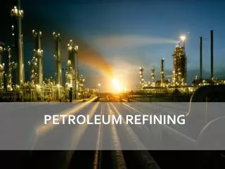
www.ProcessEngr.com Oil Refinery Processes A Brief Overview Ronald (Ron) F. Colwell, P.E. Copyright © 2009 Process Engineering Associates, LLC. All rights reserved. mol`bpp “Excellence in Applied Chemical Engineering”
Some Historical Events • 3000 BC Sumerians use asphalt as an adhesive; Eqyptians use pitch to grease chariot wheels; Mesopotamians use bitumen to seal boats 600 BC Confucius writes about drilling a 100’ gas well and using bamboo for pipes 1500 AD Chinese dig oil wells >2000’ deep 1847 First “rock oil” refinery in England 1849 Canada distills kerosene from crude oil 1856 World’s first refinery in Romania 1857 Flat-wick kerosene lamp invented 1859 Pennsylvania oil boom begins with 69’ oil well producing 35 bpd 1860-61 Refineries built in Pennsylvania and Arkansas 1870 US Largest oil exporter; oil was US 2ndbiggest export 1878 Thomas Edison invents light bulb 1901 Spindletop, Texas producing 100,000 bpd kicks off modern era of oil refining 1908 Model T’s sell for $950/T 1913 Gulf Oil opens first drive-in filling station 1942 First Fluidized Catalytic Cracker (FCC) commercialized 1970 First Earth Day; EPA passes Clean Air Act 2005 US Refining capacity is 17,042,000 bpd, 23% of World’s 73MM • • • • • • • • • • • • • • • • www.ProcessEngr.com mol`bpp Copyright © 2009 Process Engineering Associates, LLC. All rights reserved. “Excellence in Applied Chemical Engineering”
1876 California Oil Refinery www.ProcessEngr.com mol`bpp Copyright © 2009 Process Engineering Associates, LLC. All rights reserved. “Excellence in Applied Chemical Engineering”
What is Petroleum? • A complex mixture containing thousands of different organic hydrocarbon molecules – 83-87% Carbon – 11-15% Hydrogen – 1-6% Sulfur • Paraffins – saturated chains • Naphthenes – saturated rings • Aromatics – unsaturated rings www.ProcessEngr.com mol`bpp Copyright © 2009 Process Engineering Associates, LLC. All rights reserved. “Excellence in Applied Chemical Engineering”
Generic Process Schematic Naphtha Hydrotreating Hydrogen LPG Gasoline Isomerization Crude Distillation Gasoline, Aromatics Catalytic Reforming Mid-Distillate Hydrotreating Jet, Diesel Jet, Diesel Hydrocracking Crude LPG Alkylation FCC Gasoline Gasoline Cycle oil to hydrotreating or hydrocracking Vacuum Distillation Coking Asphalt Petroleum Coke www.ProcessEngr.com mol`bpp Copyright © 2009 Process Engineering Associates, LLC. All rights reserved. “Excellence in Applied Chemical Engineering”
CDU Process • Process Objective: – To distill and separate valuable distillates (naphtha, kerosene, diesel) and atmospheric gas oil (AGO) from the crude feedstock. • Primary Process Technique: – Complex distillation • Process steps: – Preheat the crude feed utilizing recovered heat from the product streams – Desalt and dehydrate the crude using electrostatic enhanced liquid/liquid separation (Desalter) – Heat the crude to the desired temperature using fired heaters – Flash the crude in the atmospheric distillation column – Utilize pumparound cooling loops to create internal liquid reflux – Product draws are on the top, sides, and bottom www.ProcessEngr.com mol`bpp Copyright © 2009 Process Engineering Associates, LLC. All rights reserved. “Excellence in Applied Chemical Engineering”
Crude Distillation Unit (CDU) Process Schematic Atmos Gas Naphtha Top Pumparound Kero Diesel Bottom Pumparound AGO Water Atmos Column Cold Preheat Hot Preheat Mix Valve Atmos Furnace Reduced Crude Crude Desalter Brine www.ProcessEngr.com mol`bpp Copyright © 2009 Process Engineering Associates, LLC. All rights reserved. “Excellence in Applied Chemical Engineering”
CDU Process • Typical Yields and Dispositions PRODUCT Yield, wt% of Crude Disposition Light Ends 2.3 LPG Light Naphtha 6.3 Naphtha Hydrotreating Medium Naphtha 14.4 Naphtha Hydrotreating Heavy Naphtha 9.4 Distillate Hydrotreating Kerosene 9.9 Distillate Hydrotreating Atmospheric Gas Oil 15.1 Fluid Catalytic Cracking Reduced Crude 42.6 Vacuum Distillation Unit www.ProcessEngr.com mol`bpp Copyright © 2009 Process Engineering Associates, LLC. All rights reserved. “Excellence in Applied Chemical Engineering”
VDU Process • Process Objective: – To recover valuable gas oils from reduced crude via vacuum distillation. • Primary Process Technique: – Reduce the hydrocarbon partial pressure via vacuum and stripping steam. • Process steps: – Heat the reduced crude to the desired temperature using fired heaters – Flash the reduced crude in the vacuum distillation column – Utilize pumparound cooling loops to create internal liquid reflux – Product draws are top, sides, and bottom www.ProcessEngr.com mol`bpp Copyright © 2009 Process Engineering Associates, LLC. All rights reserved. “Excellence in Applied Chemical Engineering”
Vacuum Distillation Unit (VDU) Process Schematic To Vacuum Jets LVGO HVGO Reduced Crude Vac Column Vac Furnace Resid www.ProcessEngr.com mol`bpp Copyright © 2009 Process Engineering Associates, LLC. All rights reserved. “Excellence in Applied Chemical Engineering”
VDU Process • Typical Yields and Dispositions PRODUCT Yield, wt% of Crude Disposition Light Ends <1 LPG Light VGO 17.6 Distillate Hydrotreating Heavy VGO 12.7 Fluid Catalytic Cracking Vacuum residue (Resid) 12.3 Coking www.ProcessEngr.com mol`bpp Copyright © 2009 Process Engineering Associates, LLC. All rights reserved. “Excellence in Applied Chemical Engineering”
Delayed Coking Process • Process Objective: – To convert low value resid to valuable products (naphtha and diesel) and coker gas oil. Primary Process Technique: – Thermocracking increases H/C ratio by carbon rejection in a semi-batch process. Process steps: – Preheat resid feed and provide primary condensing of coke drum vapors by introducing the feed to the bottom of the main fractionator – Heat the coke drum feed by fired heaters – Flash superheated feed in a large coke drum where the coke remains and vapors leave the top and goes back to the fractionator – Off-line coke drum is drilled and the petroleum coke is removed via hydrojetting • • www.ProcessEngr.com mol`bpp Copyright © 2009 Process Engineering Associates, LLC. All rights reserved. “Excellence in Applied Chemical Engineering”
Delayed Coking Process Schematic Light Ends KN LKGO HKGO Resid Coke Drums Fractionator Furnace Petroleum Coke www.ProcessEngr.com mol`bpp Copyright © 2009 Process Engineering Associates, LLC. All rights reserved. “Excellence in Applied Chemical Engineering”
Fluidic Coking Process • Process Objective: – To convert low value resid to valuable products (naphtha and diesel) and coker gas oil. Primary Process Technique: – Thermocracking increases H/C ratio by carbon rejection in a continuous process. Process steps: – Preheat resid feed, scrub coke particles, and provide primary condensing of reactor vapors by introducing the feed to the scrubber – Resid is atomized into a fluid coke bed and thermocracking occurs on the particle surface – Coke particles leaving the reactor are steam stripped to remove remaining liquid hydrocarbons – Substoichiometric air is introduced to burner to burn some of the coke and provide the necessary heat for the reactor – Reactor vapors leave the scrubber and go to the fractionator • • www.ProcessEngr.com mol`bpp Copyright © 2009 Process Engineering Associates, LLC. All rights reserved. “Excellence in Applied Chemical Engineering”
Fluidic Coking Process Schematic Light Ends HKGO Resid Scrubber KN CO Gas Burner Reactor LKGO Coke Stripper Main Fractionator Air HKGO www.ProcessEngr.com mol`bpp Copyright © 2009 Process Engineering Associates, LLC. All rights reserved. “Excellence in Applied Chemical Engineering”
Delayed & Fluid Coking Processes • Typical Yields and Dispositions PRODUCT Yield, wt% of feed Disposition Light Ends 12.5 – 20 LPG Naphtha 10 – 15 Naphtha Hydrotreating Light Coker Gas Oil 18 – 24 Distillate Hydrotreating Heavy Coker Gas Oil 30 – 40 Fluid Catalytic Cracking Pet. Coke 20 - 35 Sponge – carbon anodes; Needle – graphite electrodes; Any coke – power generation www.ProcessEngr.com mol`bpp Copyright © 2009 Process Engineering Associates, LLC. All rights reserved. “Excellence in Applied Chemical Engineering”
FCC Process • Process Objective: – To convert low value gas oils to valuable products (naphtha and diesel) and slurry oil. • Primary Process Technique: – Catalytic cracking increases H/C ratio by carbon rejection in a continuous process. • Process steps: – Gas oil feed is dispersed into the bottom of the riser using steam – Thermal cracking occurs on the surface of the catalyst – Disengaging drum separates spent catalyst from product vapors – Steam strips residue hydrocarbons from spent catalyst – Air burns away the carbon film from the catalyst in either a “partial-burn” or “full-burn” mode of operation – Regenerated catalyst enters bottom of riser-reactor www.ProcessEngr.com mol`bpp Copyright © 2009 Process Engineering Associates, LLC. All rights reserved. “Excellence in Applied Chemical Engineering”
Fluidic Catalytic Cracking (FCC) Process Schematic Products to Fractionation Disengaging Vessel Flue Gas (CO2, CO, SOx) Stripping Steam Stripper Regenerator Riser - Reactor Air Gas Oil Feed Dispersant Steam www.ProcessEngr.com mol`bpp Copyright © 2009 Process Engineering Associates, LLC. All rights reserved. “Excellence in Applied Chemical Engineering”
FCC Process • Typical Yields and Dispositions PRODUCT Yield, wt% of feed Disposition 16.5 – 22 Light Ends LPG; Alky Naphtha 44 – 56 Naphtha Hydrotreating 13 – 20 Light Cycle Oil Distillate Hydrotreating Medium Cycle Oil 10 – 26 Hydrocracking Slurry Oil 4 - 12 Heavy fuel oil; carbon black processing Coke 5 – 6 Flue gas to CO boiler www.ProcessEngr.com mol`bpp Copyright © 2009 Process Engineering Associates, LLC. All rights reserved. “Excellence in Applied Chemical Engineering”
HF Alkylation Process • Process Objective: – To combine light olefins (propylene and butylene) with isobutane to form a high octane gasoline (alkylate). Primary Process Technique: – Alkylation occurs in the presence of a highly acidic catalyst (hydroflouric acid or sulfuric acid). Process steps: – Olefins from FCC are combined with IsoButane and fed to the HF Reactor where alkylation occurs – Acid settler separates the free HF from the hydrocarbons and recycles the acid back to the reactor – A portion of the HF is regenerated to remove acid oils formed by feed contaminants or hydrocarbon polymerization – Hydrocarbons from settler go to the DeIsobutanizer for fractionating the propane and isobutane from the n-butane and alkylate – Propane is then fractionated from the isobutane; propane as a product and the isobutane to be recycled to the reactor – N-Butane and alkylate are deflourinated in a bed of solid adsorbent and fractionated as separate products • • www.ProcessEngr.com mol`bpp Copyright © 2009 Process Engineering Associates, LLC. All rights reserved. “Excellence in Applied Chemical Engineering”
HF Alkylation Process Schematic Stripped HF Isobutane Recycle Olefin Feed & Isobutane Reactor HF Stripper Depropanizer Settler Propane DeIsobutanizer Fresh Acid N-Butane HF Regenerator Debutanizer Acid Oils Deflourinator Alkylate www.ProcessEngr.com mol`bpp Copyright © 2009 Process Engineering Associates, LLC. All rights reserved. “Excellence in Applied Chemical Engineering”
HF Alkylation Process • Typical Yields and Dispositions PRODUCT Yield, vol% of olefin feed Disposition Propane 20 - 30 LPG 40 - 52 N-Butane LPG; Gasoline Alkylate 150 – 170 Gasoline Acid Oils <1 Furnace Isobutane consumption 67 - 75 www.ProcessEngr.com mol`bpp Copyright © 2009 Process Engineering Associates, LLC. All rights reserved. “Excellence in Applied Chemical Engineering”
Hydrotreating Process • Process Objective: – To remove contaminants (sulfur, nitrogen, metals) and saturate olefins and aromatics to produce a clean product for further processing or finished product sales. Primary Process Technique: – Hydrogenation occurs in a fixed catalyst bed to improve H/C ratios and to remove sulfur, nitrogen, and metals. Process steps: – Feed is preheated using the reactor effluent – Hydrogen is combined with the feed and heated to the desired hydrotreating temperature using a fired heater – Feed and hydrogen pass downward in a hydrogenation reactor packed with various types of catalyst depending upon reactions desired – Reactor effluent is cooled and enter the high pressure separator which separates the liquid hydrocarbon from the hydrogen/hydrogen sulfide/ammonia gas – Acid gases are absorbed from the hydrogen in the amine absorber – Hydrogen, minus purges, is recycled with make-up hydrogen – Further separation of LPG gases occurs in the low pressure separator prior to sending the hydrocarbon liquids to fractionation • • www.ProcessEngr.com mol`bpp Copyright © 2009 Process Engineering Associates, LLC. All rights reserved. “Excellence in Applied Chemical Engineering”
Hydrotreating Process Schematic Recycle Compressor Make-up Compressor Quench H2 Make-up Hydrogen Purge Hydrogen Reactors H2S Acid Gas Fired Heater HP Amine Absorber Feed/Effluent Exchanger Feed High Pressure Separator LPG Low Pressure Separator Effluent Cooler Product to Fractionator www.ProcessEngr.com mol`bpp Copyright © 2009 Process Engineering Associates, LLC. All rights reserved. “Excellence in Applied Chemical Engineering”
Hydrotreating Process • Naphtha Hydrotreating – Primary objective is to remove sulfur contaminant for downstream processes; typically < 1wppm Gasoline Hydrotreating – Sulfur removal from gasoline blending components to meet recent clean fuels specifications Mid-Distillate Hydrotreating – Sulfur removal from kerosene for home heating – Convert kerosene to jet via mild aromatic saturation – Remove sulfur from diesel for clean fuels • Ultra-low sulfur diesel requirements are leading to major unit revamps FCC Feed Pretreating – Nitrogen removal for better FCC catalyst activity – Sulfur removal for SOxreduction in the flue gas and easier post-FCC treatment – Aromatic saturation improves FCC feed “crackability” – Improved H/C ratios increase FCC capacity and conversion • • • www.ProcessEngr.com mol`bpp Copyright © 2009 Process Engineering Associates, LLC. All rights reserved. “Excellence in Applied Chemical Engineering”
Hydrocracking Process • Process Objective: – To remove feed contaminants (nitrogen, sulfur, metals) and to convert low value gas oils to valuable products (naphtha, middle distillates, and ultra-clean lube base stocks). Primary Process Technique: – Hydrogenation occurs in fixed hydrotreating catalyst beds to improve H/C ratios and to remove sulfur, nitrogen, and metals. This is followed by one or more reactors with fixed hydrocracking catalyst beds to dealkylate aromatic rings, open naphthene rings, and hydrocrack paraffin chains. Process steps: – Preheated feed is mixed with hot hydrogen and passes through a multi-bed reactor with interstage hydrogen quenches for hydrotreating – Hydrotreated feed is mixed with additional hot hydrogen and passes through a multi-bed reactor with quenches for first pass hydrocracking – Reactor effluents are combined and pass through high and low pressure separators and are fed to the fractionator where valuable products are drawn from the top, sides, and bottom – Fractionator bottoms may be recycled to a second pass hydrocracker for additional conversion all the way up to full conversion • • www.ProcessEngr.com mol`bpp Copyright © 2009 Process Engineering Associates, LLC. All rights reserved. “Excellence in Applied Chemical Engineering”
Hydrocracking Process Schematic Make-up Compressor Make-up Hydrogen Fired Heater Purge Hydrogen Recycle Compressor H2S Acid Gas HP Amine Absorber Hydrotreating Reactor 1stPass Hydrocracking Reactor 2ndPass Hydrocracking Reactor High Pressure Separator LPG Low Pressure Separator Feed Recycle/Effluent Exchanger Feed/Effluent Exchanger Product to Fractionator Effluent Cooler Recycle From Fractionator Bottoms www.ProcessEngr.com mol`bpp Copyright © 2009 Process Engineering Associates, LLC. All rights reserved. “Excellence in Applied Chemical Engineering”
Hydrocracking Process • Typical Yields and Dispositions PRODUCT Yield, vol% feed Disposition Light ends Varies depending upon objectives LPG Naphtha “” Gasoline; Catalytic Reformer Diesel “” Diesel Total volume yield 130 - 140 Gas oil conversion 60 – 99% www.ProcessEngr.com mol`bpp Copyright © 2009 Process Engineering Associates, LLC. All rights reserved. “Excellence in Applied Chemical Engineering”
Catalytic Reforming Process • Process Objective: – To convert low-octane naphtha into a high-octane reformate for gasoline blending and/or to provide aromatics (benzene, toluene, and xylene) for petrochemical plants. Reforming also produces high purity hydrogen for hydrotreating processes. Primary Process Technique: – Reforming reactions occur in chloride promoted fixed catalyst beds; or continuous catalyst regeneration (CCR) beds where the catalyst is transferred from one stage to another, through a catalyst regenerator and back again. Desired reactions include: dehydrogenation of naphthenes to form aromatics; isomerization of naphthenes; dehydrocyclization of paraffins to form aromatics; and isomerization of paraffins. Hydrocracking of paraffins is undesirable due to increased light-ends make. Process steps: – Naphtha feed and recycle hydrogen are mixed, heated and sent through successive reactor beds – Each pass requires heat input to drive the reactions – Final pass effluent is separated with the hydrogen being recycled or purged for hydrotreating – Reformate product can be further processed to separate aromatic components or be used for gasoline blending • • www.ProcessEngr.com mol`bpp Copyright © 2009 Process Engineering Associates, LLC. All rights reserved. “Excellence in Applied Chemical Engineering”
Catalytic Reforming Process Schematic 3rdPass Reactor 2ndPass Reactor 1stPass Reactor Naphtha Feed 2ndPass Heater 1stPass Heater 3rdPass Heater Recycle Compressor High Purity Hydrogen HP Separator LPG LP Separator Reformate to Fractionation www.ProcessEngr.com mol`bpp Copyright © 2009 Process Engineering Associates, LLC. All rights reserved. “Excellence in Applied Chemical Engineering”
Catalytic Reforming Process • Typical Yields and Dispositions PRODUCT Yield, vol% feed Disposition Light ends 5 – 8 LPG Reformate 84 – 85 Gasoline; Petrochemical Plants Hydrogen 650 – 1100 scf/bbl Hydrotreating www.ProcessEngr.com mol`bpp Copyright © 2009 Process Engineering Associates, LLC. All rights reserved. “Excellence in Applied Chemical Engineering”
Isomerization Process • Process Objective: – To convert low-octane n-paraffins to high-octane iso-paraffins. Primary Process Technique: – Isomerization occurs in a chloride promoted fixed bed reactor where n-paraffins are converted to iso-paraffins. The catalyst is sensitive to incoming contaminants (sulfur and water). Process steps: – Desulfurized feed and hydrogen are dried in fixed beds of solid dessicant prior to mixing together – The mixed feed is heated and passes through a hydrogenation reactor to saturate olefins to paraffins and saturate benzene – The hydrogenation effluent is cooled and passes through a isomerization reactor – The final effluent is cooled and separated as hydrogen and LPGs which typically go to fuel gas, and isomerate product for gasoline blending • • www.ProcessEngr.com mol`bpp Copyright © 2009 Process Engineering Associates, LLC. All rights reserved. “Excellence in Applied Chemical Engineering”
Isomerization Process Schematic Desulferized n-Paraffin Feed Dryer Heater Hydrogenation Reactor Hydrogen Dryer Hydrogen and LPG Isomerization Reactor Separator Isomerate Product to Gasoline www.ProcessEngr.com mol`bpp Copyright © 2009 Process Engineering Associates, LLC. All rights reserved. “Excellence in Applied Chemical Engineering”
Isomerization Process • Typical Yields and Dispositions PRODUCT Disposition Hydrogen and Light ends LPG, Fuel gas Isomerate Gasoline; iso-butane for Alkylation Conversion Up to 97% www.ProcessEngr.com mol`bpp Copyright © 2009 Process Engineering Associates, LLC. All rights reserved. “Excellence in Applied Chemical Engineering”
Generic Process Schematic Naphtha Hydrotreating Hydrogen LPG Gasoline Isomerization Crude Distillation Gasoline, Aromatics Catalytic Reforming Mid-Distillate Hydrotreating Jet, Diesel Jet, Diesel Hydrocracking Crude LPG Alkylation FCC Gasoline Gasoline Cycle oil to hydrotreating or hydrocracking Vacuum Distillation Coking Asphalt Petroleum Coke www.ProcessEngr.com mol`bpp Copyright © 2009 Process Engineering Associates, LLC. All rights reserved. “Excellence in Applied Chemical Engineering”
1948 FCC and Crude Distillation www.ProcessEngr.com mol`bpp Copyright © 2009 Process Engineering Associates, LLC. All rights reserved. “Excellence in Applied Chemical Engineering”