Download
1 / 34
360 likes | 719 Views
John H. Kerr Dam and Reservoir. U.S. Army Corps of Engineers Wilmington District. John H. Kerr Dam and Reservoir. U.S. Army Corps of Engineers Wilmington District. John H. Kerr Dam and Reservoir. U.S. Army Corps of Engineers Wilmington District. Project Purposes

E N D
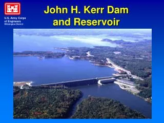
John H. Kerr Dam and Reservoir U.S. Army Corps of Engineers Wilmington District
John H. Kerr Dam and Reservoir U.S. Army Corps of Engineers Wilmington District
John H. Kerr Dam and Reservoir U.S. Army Corps of Engineers Wilmington District • Project Purposes • Flood Control (PL 78-534, Flood Control Act of 1944) • Hydroelectric Power (PL 78-534) • Recreation (PL 78-534) • Water Supply (PL 85-500) • Fish and Wildlife (PL 85-624) • Low Flow Augmentation (PL 78-534) no longer required because of FERC Project license number 2009 for Gaston and Roanoke Rapids
John H. Kerr Dam and Reservoir U.S. Army Corps of Engineers Wilmington District • Pertinent Information • Large interest in flood control following the August 1940 flood resulted in authorization of John H. Kerr • Construction Contract was awarded April 1948 • Construction completed in June 1951 • Filling began on 30 June 1952 • Watershed drainage area of 7800 square miles • Reservoir Surface Area at Elev. 300 of 48,900 acres • Length of Shoreline at Elev. 300 of 800 miles
John H. Kerr Dam and Reservoir U.S. Army Corps of Engineers Wilmington District • Pertinent Information • Top of Dam at elevation 332 • Lowest portion of dam is at elevation 188 • 22 tainter flood gates 42’ wide by 32’ tall • Tainter gate discharge capacity at 320 is 615,000 cfs • 6 turbines rated at 32,000 kw each • 1 turbine rated at 12,000 kw • 2 station service units rated at 1,000 kw each • Turbine Discharge Capacity originally was 34,000 cfs
John H. Kerr Dam and Reservoir U.S. Army Corps of Engineers Wilmington District • The structure of John H. Kerr Dam required: • 624,244 cubic yards of concrete, • 1,200,000 tons of sand and crushed stone, • 7,550,941 pounds of reinforcing steel, • 1,317,786 pounds of structural steel, • 578,440 barrels of cement and • 515,286 pounds of miscellaneous steel and iron
John H. Kerr Dam and Reservoir What were the effects of the changed guide curve?
John H. Kerr Dam and Reservoir Flood Control Operation
John H. Kerr Dam and Reservoir Power Pool Operation
John H. Kerr Dam and Reservoir U.S. Army Corps of Engineers Wilmington District
John H. Kerr Reservoir—Zone A Operation Zone A (Interchange Zone)—The sum of the minimum contract energy amounts are being met by the Kerr-Philpott system in toto. The project having the higher percent of hydropower storage remaining produces the higher portion of total minimum contract energy. Typically enough energy is being produced at each project to meet minimum flow commitments downstream.
John H. Kerr Reservoir—Zone B Operation Zone B (Below Guide Curve)—Kerr minimum contract energy amounts are being met by the Kerr project. If Philpott reservoir is in a flood status, then part of Kerr’s minimum contract energy will be picked up by Philpott. Enough energy is being declared and turbine discharge produced to provide minimum downstream flow needs.
John H. Kerr Dam—Zone C Operation Zone C (Above Guide Curve But Below Bottom of Flood Control Pool)—Minimum energy amounts are being met by the Kerr project. If inflows are high or Kerr Reservoir is high enough above the guide curve, then extra energy and turbine releases are declared. However, releases are not to exceed 8,000 cfs from the Roanoke Rapids Dam into the lower Roanoke River.
John H. Kerr Dam—Zone D Operation Zone D (Striped Bass Spawn Storage)—Striped bass spawn target flows downstream are made by Kerr Dam and then by Roanoke Rapids Dam. Target flows are bound by a lower, median and upper flow threshold.
John H. Kerr Dam—Zone E1 Operation Zone E1 (300 – 312, Lower Controlled Flood Pool)—Will hold 1.64 inches of rainfall runoff. Turbine releases of up to 20,000 cfs are made at Kerr Dam. Releases of 20,000 cfs are made at the Roanoke Rapids Dam. This is full turbine plant at the Roanoke Rapids Dam.
John H. Kerr Dam—Zone E2 Operation Zone E2 (312 – 315, Middle of Controlled Flood Pool)—Will hold 0.49 inches of rainfall runoff. Turbine releases of up to 25,000 cfs are made at Kerr Dam. Releases of 25,000 cfs are made at the Roanoke Rapids Dam. This is full turbine plant at the Roanoke Rapids Dam plus a spill of 5,000 cfs through the spillway gates.
John H. Kerr Dam—Zone E3 Operation Zone E3 (315 – 320, Upper Part of Controlled Flood Pool)—Will hold 0.95 inches of rainfall runoff. Turbine releases and tainter gate (spillway) releases of up to 35,000 cfs are made at Kerr Dam. Releases of 35,000 cfs are made at the Roanoke Rapids Dam. This is full turbine plant at the Roanoke Rapids Dam plus a spill of 15,000 cfs through the spillway gates.
John H. Kerr Dam—Zone E4 Operation Zone E4 (320 – 321, Lower Uncontrolled Flood Pool)—Will hold 0.22 inches of rainfall runoff. Turbine releases and tainter gate releases of 85 percent of inflow to Kerr Dam are made in the lower Roanoke River from Roanoke Rapids Dam. Releases will be greater than or equal to 35,000 cfs from RR Dam. Lake Gaston will be surcharged.
John H. Kerr Dam—Zone E5 Operation Zone E5 (Kerr is Greater than El. 321 - Upper Part of Uncontrolled Flood Pool)—Tainter gate releases of 100 percent of inflow to Kerr Dam are made in the lower Roanoke River from Roanoke Rapids Dam. Releases from Roanoke Rapids Dam will be equal to or greater than 35,000 cfs.
John H. Kerr Dam and Reservoir Upstream and Downstream Users U.S. Army Corps of Engineers Wilmington District
John H. Kerr Dam and Reservoir Upstream verses Downstream Operational Conflict Example U.S. Army Corps of Engineers Wilmington District • Upstream Recreation verses Downstream Recreation: Upstream recreation interests prefer a stable lake level with inflows passed downstream unbuffered whether they are large or small. Downstream recreation interests prefer a steady river in which to fish and boat. This means storing flood waters behind Kerr Dam with high lake levels which impact upstream recreation users. This also means lower reservoir levels during drought events when extra water is released from Kerr Reservoir to boost downstream river levels.
John H. Kerr Dam and Reservoir Upstream verses Downstream Flood Release Operational Conflict U.S. Army Corps of Engineers Wilmington District • Upstream Hydropower verses Downstream Hydropower: Upstream: The turbines at Kerr Dam can pass about 33,000 cfs during a flood event. Downstream: The turbines at the Dominion Roanoke Rapids Dam located downstream can only pass flows up to 20,000 cfs and have to spill additional flood releases with a loss of hydropower generation and a loss of revenue. Dominion would prefer capping flood releases at Kerr Dam to an average of 20,000 cfs.
John H. Kerr Dam and Reservoir Downstream verses Downstream Flood Release Operation Conflict U.S. Army Corps of Engineers Wilmington District • Downstream Timber Harvesting, Hunters and Fishing Interests: Prefer flood releases to be capped at 8,000 cfs (river channel capacity). But if the flood storage in Kerr Reservoir is threatened, then 35,000 cfs or higher would be ok to limit the duration of the flood plain flooding. • Downstream Agricultural Interests: Prefer capping long term flows at 20,000 cfs. Flows greater than 20,000 cfs impact crop and grazing lands and flood farm roads. Some farm lands may be impacted at flows exceeding 12,000 cfs.
John H. Kerr Dam and Reservoir Operational Conflict For Downstream verses Downstream Continued……. U.S. Army Corps of Engineers Wilmington District • Downstream Non-agricultural Interests: These interests could withstand flows possibly up to 45,000 cfs during extreme floods without damage to property. Preference is to see flows to about 40,000 cfs to reduce duration of flood flows. • Downstream Prison Farm: Earthen dike protects this area that would be threatened by flows of 35,000 cfs and overtopped by flows of 40,000 cfs. Preference is to wisely use the controlled flood storage behind Kerr to prevent large flood releases.
John H. Kerr Dam and Reservoir Project Accomplishments U.S. Army Corps of Engineers Wilmington District • Flood Damages Prevented • $390,852,800 total since filling • Average Annual Hydropower Generation • 433,817,800 kWH • Typical Annual Recreational Visitation • Range is from 3 to 4 million visitors
John H. Kerr Dam and Reservoir Striped Bass Spawn Success U.S. Army Corps of Engineers Wilmington District
John H. Kerr Dam and Reservoir U.S. Army Corps of Engineers Wilmington District
John H. Kerr Dam and Reservoir U.S. Army Corps of Engineers Wilmington District
John H. Kerr Dam and Reservoir U.S. Army Corps of Engineers Wilmington District