Download
1 / 43
580 likes | 1.12k Views
Fractional PI controller in liquid level & flow control Experimental study on Coupled Tank System. Varsha Bhambhani Graduate Research Assistant Center of Self Organizing and Intelligent Systems (CSOIS) Electrical Engineering Department, Utah State University, Logan, USA.

E N D
Fractional PI controller in liquid level & flow controlExperimental study on Coupled Tank System Varsha Bhambhani Graduate Research Assistant Center of Self Organizing and Intelligent Systems (CSOIS) Electrical Engineering Department, Utah State University, Logan, USA
Liquid Level & Flow Control Common control problem in Water-treatment plants, Petro-chemical industries and other process industries. Human blood circulating system is another classic example of liquid level & flow control. Coupled Tank System: An important laboratory and teaching level instrument present in many universities which helps in study of design, operation and applications of common controllers. Benefits:- Useful in system modeling based on static and dynamic control study, steady state and transient behavior analysis, controller design and controller tuning method study. Working:- a) compact , bench top instrument consisting of two water tanks made of perplex seated on a water reservoir which stores water. b) A baffle plate can be slided up & down to vary interaction or coupling dynamics between two tanks. c) Two PWM operated motor pumps use either 0-5V analog voltage (internal signal conditioning system covert analog to PWM (digital) signals) or external PWM sources for their operation. Flow rates of water into tanks can be varied by change of these pump voltages.
Coupled Tank System – Specifications contd. d)Two capacitive probes, one in each tank ,provided to measure water level. Output signals from these probes are conditioned to give 0-5V DC analog output. e) A water outlet at side near base of each tank connected by a flexible tube returns water to reservoir. f) Two potentiometers at back side of CTS are provided for manual operation of motors.
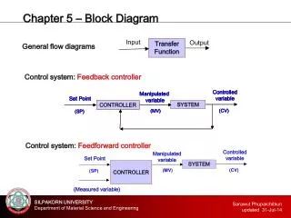
Cases Studied A comparison of Integer and fractional Proportional Integral (PI) Controller is made. In general a PI controller has following effects: add damping improve the steady-state error the rise time and settling time are penalized For this three configurations of Coupled Tank System are studied: First order Single Input Single Output (SISO) plants. A second Order SISO plant. Cascaded control plant. Each case involves: Brief description of system modeling. Real time System identification. Controller design. Experiments & simulations. Comments.
Case I :- First order Single Input Single Output (SISO) plants. System modeling: When baffle plate is lowered completely, two tanks operate independently as first order single input single output (SISO) systems. Relation between water entering and leaving tank is expressed as:- Where, is water flow in tank Is water flow out of tank A is cross-sectional area of tank H is height of water in tank The output flow through the valve is related to the water level in the tank by the relation:-
Case I contd. Where, C is discharge coefficient of the valve. And a is the area of cross section of the orifice. And g is gravitational constant 9.8 m/s^2. Summarizing we get, Above non-linear equation describes the system behavior of first order SISO system. Real time system identification: In terms of transfer function, in real time, the manipulated variable/plant input is pump input voltage and process variable/plant output is water level in the tank. The transfer function of first order SISO system is given by:
Case I contd. Where, K is the gain of the system, is the time constant and L is the delay of the system. One can either do frequency response analysis or step response analysis to identify transfer function. Frequency response Analysis of first order SISO plant. Procedure: Apply sinusoidal input at different frequencies to the open loop control plant and observe the gain and the phase shift at steady state. Sinusoidal input:-
Real Time Experimental Setup A typical feedback control system will have the following components: the Plant, Sensors, Actuators and a Controller. In a digital real-time control application the analog controller is replaced by the digital computer (PC). They give the flexibility of changing the program according to the change in design requirements or dynamics of the system. The digital controller needs feedback from the plant in the appropriate format which is ensured by the DACB (Data Acquisition and Control boards) provided by Quanser.
Q4 Hardware In Loop Board from Quanser Key Features • 4 x 14-bit analog inputs • 4x 12-bit D/A voltage outputs • 4 quadrature encoder inputs • 16 programmable digital I/O channels • Simultaneous sampling of both analog and encoder sections • 2x 32-bit dedicated counter/timers • 4x 24-bit reconfigurable encoder counter/timers • 2x on-board PWM outputs • 32-bit, 33 MHz PCI bus interface • Supports Quanser real-time control software WinCon (2000/XP) • Totem Pole digital I/O for high speed • Easy synchronization of multiple Q4 boards
Real time control of hardware in loop • These boards accept the sensor signals from the plant and convert them to digital signals which is then sent back to the computer. • The code which emulates the controller computes on this data and decides the next set of control signals and sends digital data to the DACB which converts it to an analog signal, sent to the actuators. • All these operations are performed in real-time and this is achieved by the real-time Windows2000 /XP application WinCon which runs in real-time the C code generated for the control law imple--mented in MATLAB/ Simulink Real Time Workshop.
Case I :- Frequency response Analysis of first order system & block settings
Results of frequency response analysis of first order system (diff freq considered)
Inputs that are not manipulated, classified as disturbance or load variable result in differences between extracted bode plot data & experimental data
Case I :- closed loop system response first order system & block settings/Controller Design
Controller design/ Tuning rules • Integer Order Proportional Integral Controller (PI) tuned by: • Ziegler Nichol’ s Method • Modified Ziegler Nichol’s Method • Method[Kc,Pm,wc,wp] = margin(G); • Tc = 2*pi/wc; • Fractional Order Proportional Integral Controller (FOPI) tuned by : Fractional Ms constrained Integral Gain (FMIGO) Method
Comments on First Order SISO Coupled Tank Experiments • Real time system results are in accordance with the simulation results with little difference which can be accounted due to uncontrollable real time environmental disturbances. • Both simulated and real time results confirm that the percentage overshoot is minimum in FOPI (FMIGO) method, though this is at the expense of slow response time when compared with integer order PI-ZN and PI-MZN methods. • Thus results of first order SISO coupled tank experiments clearly shows that a fraction order controller is a promising controller for water level and flow control.
Case II :- Second order Single Input Single Output (SISO) plants. System modeling: When baffle plate is raised, water flows from one tank to another. The target is to maintain a fixed level of water in second tank by varying voltage input to first tank. The control system has two states, levels in two tanks, i.e. in tank 1 and in tank2. , pump flow to tank 1, is the control input. , water level in tank 2, is output. Valve B and C account for load disturbances. The equation of water flow balance in tank 1 is given by: is water flow from tank 1 to tank 2.
Cases II contd. The water flow balance equation for tank 2 is given by: is flow of water out of tank 2 through valve C. Assuming orifices to be ideal, the non- linear ties are computed by square root law in substituted in above equations as:- Above non-linear equations are linear zed further to obtain state equation of the coupled tank system. The transfer equation for second order SISO system is given by :
Case II contd. Where, K is the process gain of the system, is the damping ratio and is defined as degree of oscillation in the process response after a perturbation. is the natural frequency of the system is the inverse of time constant which determines the speed of response of the system. Analyzing the denominator, we get: The roots of the characteristic equation are:
Case II contd. Three cases arise as shown in table above: One can either do frequency response analysis or step response analysis to identify transfer function. Frequency response Analysis of first order SISO plant. Procedure: Apply sinusoidal input at different frequencies to the open loop control plant and observe the gain and the phase shift at steady state. The real time experimental setup is shown in next slide. The block diagram and the different block settings for frequency analysis is shown in next to next slide.
Case II:- Frequency response Analysis of Second order system & block settings
Results of frequency response analysis of second order system (diff freq considered)
Approximation of second order transfer function by first order transfer function using getfod file
Case I I :- closed loop system response second order system & block settings/Controller Design
Comments on second Order SISO Coupled Tank Experiments • Real time system results are in accordance with the simulation results with little difference which can be accounted due to uncontrollable real time environmental disturbances. • It is seen that in case of second order SISO system, FOPI (FMIGO) results in large overshoot when compared with integer order PI-ZN and PI-MZN method but then the response time is much less when compared to other controllers. • Thus results of second order SISO coupled tank experiments clearly shows that a fraction order controller is a promising controller for water level and flow control.
Case III :- Cascaded control plant system. System modeling: This type of control system has two cascaded controllers namely primary and secondary controllers. The controlled variable is water flow to tank1. The master controller decides the set point of the slave controller. The slave controller tries to track the set point. The master controller uses water level in tank 2 as process variable by varying water level in tank1. Suitable baffle opening between two tanks introduces significant time separation between the two controllers which minimizes the effect of disturbance in water level of tank 1 to water level of tank 2.
Case III contd. Both cascaded plants are configured as first order transfer function namely primary and secondary plants having transfer function in general form as Where, K is the gain of the system, is the time constant and L is the delay of the system. One can either do frequency response analysis or step response analysis to identify transfer function. Instead of doing frequency response twice for each plant ( which is time consuming), one can do step response in which step input is applied to the plant and the response recorded . Step Input:-
Case III:- Step response Analysis of Cascaded plants & block settings
Results of step response analysis of two cascaded plants An input step of 2V is applied and step response of tank1(secondary tank) and tank2(primary tank) recorded in real time. The transfer function two plants computed from step responses are:
Case III :- closed loop system response cascaded control plants & block settings/Controller Design
Comments on Cascaded control plant Coupled Tank Experiments • Real time system results are in accordance with the simulation results with little difference which can be accounted due to uncontrollable real time environmental disturbances. • It is seen that in case of real time system, FOPI (FMIGO) controller in time interval 600-1000 seconds gives no overshoot and is an ideal controller when compared with integer order PI-ZN,PI-MZN method. • Thus results of cascaded control plants coupled tank experiments clearly shows that a fraction order controller is a promising controller for water level and flow control.
Results of Experimental study 1_) A very intensive study showing system identification, controller design of coupled tank system was performed. 2) A thorough comparison between the three controllers were made. • Results show that FOPI(FMIGO) is a promising controller in process industries and can even perform better at some point when compared with integer order PI controllers. 4) Major problems in real time controller design seen are due to: Transient response design is hard: a) Robustness is always an issue - Modeling uncertainty. - Parameter variations. - Disturbances. b) Lack of theory (design uncertainty) - Relation between pole/zero locations and transient response. - Relation between Q/R weighting matrices in optimal control and transient response.