Download
1 / 34
340 likes | 489 Views
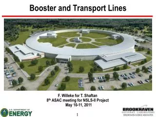
Booster and Transport Lines. F. Willeke for T. Shaftan 8 th ASAC meeting for NSLS-II Project May 10-11, 2011. Outline. Introduction Project baseline dates Status of the booster system Magnets and supports Power supplies Vacuum system Diagnostics and instrumentation Infrastructure

E N D
Booster and Transport Lines F. Willeke for T. Shaftan 8th ASAC meeting for NSLS-II Project May 10-11, 2011
Outline Introduction Project baseline dates Status of the booster system Magnets and supports Power supplies Vacuum system Diagnostics and instrumentation Infrastructure Status of the transport lines Risks and their mitigation plans Conclusions
NSLS-II injector Injection straight B-SR TL 3-GeV booster, C=158m 20 mA, 1 Hz, 40 nmrad 200-MeV linac 15 nC/160-300 ns, 0.5% e.s., 50 µmrad LB TL 4
Introduction • Injector building BOD 26 July 2011 • Booster contract was awarded to BINP in May 2010 • Booster PDR took place in October 2010 • Booster FDR took place in February 2011; >700 pages, drawing package • Booster 1st articles due date 2 July 2011. They include: • BD, BF, Q, S, corrector magnets; • First complete girder; • Beam pick-up electrodes; • Sextupole and corrector PSs; • a kicker. • Transport lines are being developed by NSLS-II • LtB design review took place in Jan 2011; LtB TL design is completed • Most of LtB TL elements are in procurement • BSR TL design is being finalized.
Booster and transport lines in the Injector building Courtesy of M. Johanson
Baseline project dates • Comments • LtB TL inside the linac vault will be installed prior to the linac commissioning • Short diagnostic line near booster extraction has to be in place prior to the booster commissioning
Materials, tooling All ordered materials (steel, copper, etc.) arrived to BINP Press form for arc vac. chambers is ready Stacking fixture for BF magnets and stamping tool for lamination production for BD mag.
Booster magnets Sextupole magnet complete 3D model April 14th: first half of the BF dipole and 1st coil are complete! Half of total num of sextupole segments is already produced Assembled quadrupole and it’s coils
Booster dipoles: magnetic measurements • Magnetic measurements of the booster dipoles are challenging • Combined-function dipoles with strong quad gradient and sextupoles • Hall probe array is moving along straight rail through dipoles • The system will be ready in mid-May Measurement cart with Hall probe array Tests of mag meas system with laser tracker in CMM lab at BINP
Magnet production • 60% of quadrupoles yokes are available • almost all laminations for quads and sextupoles are cut • coils for all magnets are now in mass production • accessories are being purchased in a large lot • magnet footings are in the manufacturing plant • BINP plant takes the booster contract as high-priority
Supports, vacuum chambers Girder tables are being produced • Arc vacuum chambers are formed • Regular pipe is filled with H2O under pressure and pressed in the form • Chamber shapes were checked in CMM machine • Chamber baking station (4.5 m long chambers) is ready to receive assemblies Chamber baking station
Diagnostics and Instrumentation • Design of the diagnostics and instrumentation system is complete • All BPM buttons are on order; 5 BPM buttons were procured from MPF and shipped to BINP for prototyping • The booster BPM system will be using NSLS-II electronics that Diag&Instrum. group at NSLS-II will supply once development is complete • Bergoz transformers are on order • 6 Beam screens were designed by BINP and approved by NSLS-II, currently are in manufacturing plant • Diagnostics cabling and cable trays are designed; BPM cables are low-loss and will run in shielded tray. Bergoz NPCT-CF4.5"-60.4-120-UHV-H
Power supplies • In Dec 2010 Danfysik has received the contract on 3 dipole PS with energy storage units (layout above: DPS final design). Now in production. • 1st article of Corrector/ Sextupole PS is ready (photo on above right ) • Quadrupole PS: Converter Mains, Invertor units are ready, Rectifier and Current Sources are close to completion. • All 1st articles will be available in May for testing
Pulsed power systems Matching “Smart” copper coil a-la BINP design Thyratron Ferrite kicker mock-up PClipper PFN 200 ns rise, 300 ns flattop pulse • Injection/ Extraction kicker prototype is ready • These are the most difficult PM systems in the project • Design and technology were developed and proven at BINP and at PML at NSLS-II • The kicker performance corresponds to the specification; production of all 6 systems has commenced.
Power supply enclosures • Cabinet for injection/ extraction septa • Currently in manufacturing plant • Power supply rack • Empty racks are delivered to BINP in March
Booster RF straight section 500 MHz 7-cell cavity RF straight interfaces between BINP and NSLS-II See presentation by Jim Rose
Infrastructure, procurement status • Design of cabling and cable trays is complete • Design has been presented at FDR in 1:1 model and approved by NSLS-II Electrical group with some changes • NSLS-II Electrical group will install the trays and pull/ terminate the cables starting from August 2011 • Booster water system is approved by NSLS-II and procurement of water pipes and accessories is to begin shortly • Design of the booster compressed air system (valves, beam screens) is being finalized • The booster girders will arrive preassembled as to minimize assembly at NSLS-II and will require attaching legs to girders and connection to the infrastructure in place Cabling of Quadrupole families Booster tunnel cross-section
Other project activities and plans • Procurement list NSLS-II BINP is finalized; > 100 positions; POs are in flux • Action item lists are maintained up-to-date • Weekly tele-cons are scheduled; in fact they proceed on as-needed basis • Export Control issues are being resolved • Active exchange of NSLS-II and BINP visitors • 2 BINP designers are working at BNL for a month on finalizing booster/TL interfaces • BINP controls staff is staying at NSLS-II for programming PSI/PSC/PLC and developing HLAs • Injector building BOD date is July 26th 2011; Installation of electrical and mechanical infrastructure will begin as soon as the building is available; Visits of BINP staff responsible for booster infrastructure and survey/ alignment are scheduled in August. • 1st articles acceptance testing is scheduled on 1 and 2 week of July (right on schedule). • Visit to Danfysik is expected in August/ September time frame
Introduction • Transport lines will be developed and integrated by NSLS-II • TL magnet contract was awarded to Stangenes in Oct 2010 • TL beam screens contract was awarded to Radiabeam in March 2011 • Vendors for the supports, vac. equipment are identified • Standard beam line components are in procurement • Supplemental shielding design is completed at 85% for LtB TL • Delivery of all required LtB TL components is scheduled before the linac installation
Booster injection and extraction • Transport line interfaces are currently being finalized. • NSLS-II/BINP designers are working together.on final design. Booster injection straight and LtB Booster extraction straight and BSR TL Courtesy of R. Fliller and M. Johanson
LtB TL Dipole magnet • Transport line Magnet DVR completed in February 2011 • The magnetic design of LtB TL magnets complete • Steel laminations to be manufactured by laser cutting • All steel and copper has been ordered. • Steel for all the corrector magnets has arrived. • Detailed design of winding mandrels for dipole and quadrupole coils are underway; some are being fabricated • Design efforts are underway at Stangenes on a Hall probe mapping system to determine dipole, quadrupole and corrector magnet field quality. • Stangenes is now working two shifts in both their machine shop and coil winding shop, this will significantly improve their manufacturing capability for their BNL job Transport Line magnets Courtesy of J. Skaritka
Booster and TL Vacuum Systems • Linac-Booster Transport Line • Layout finalized, detail component design underway • B1, B3 & B4 chambers fabricated, B2 design completed • Booster Ring • Arc chamber fabrication started by BINP • Straight section detail design & TL interface underway • Pumps, valves, gauges and controllers purchased by BNL • PLC layout and logic developed together with BINP • Booster-Storage Ring Transport Line • Layout and bending chamber design underway LtB dipole vacuum chamber Courtesy of D. Hseuh
LBT Supports Status • The purchase order for all ground steel plates for all supports (Phase-I Installation) except Dump-1 & Dump-2 has been placed. • The requisition for all LBT Support Frames (Phase-I Installation) except Dump-1 and support in booster vault has been placed. • Central shop will do all machining on support top plates. • The work is being performed to finalize the shielding of Dump-1 and Dump-2. The support and top plates for Dump-1 & Dump-2 will be ordered after shielding is finalized next week. • The expected delivery time for all supports is second week of June, 2011. • The expected completion time for complete support assembly with plates is first week of July, 2011. One of LtB support tables Courtesy of A. Hussain and B. Kosciuk
Transport line diagnostics Ordered/In development Courtesy of D. Padrazo, O. Singh, I .Pinayev
Transport Line Controls • Two clusters in order: the development cluster and production cluster. The source code for application is developed and maintained on the development cluster. Only the executable image and support file are moved to the production cluster. • The software environment is mainly built (not limited) around Python, PyQt for the GUI. The machine information is displayed using CSS (BOY). • Virtual machine: ready for LtB (including LtD1 and LtD2) transport line. The source code is developed and tested in the virtual machine. The virtual machine status can be read/set with command caget/caput. • Channel finder: ready for LtB transport line, in Python and CSS environment. • Twiss server: under development with Tracy and Elegant. Online Twiss server provides Twiss parameters, 6*6 transfer matrix and orbit. Offline Twiss server function is more diverse, depending on the applications. • The IRMIS database: under development. • High level applications: mostly under the specifications stage. The emittance measurement source code is under test with virtual machine. • Machine display panel: under development. Courtesy of G. Wang, B. Dalesio, G. Shen, K. Shroff, J. Hu
Booster-to-Storage Ring transport line • Booster-to-Storage ring transport line is complete at final design stage • We are beginning to populate the drawing with the actual element layouts watching for interferences • in the past months we were focusing on LtB TL as needed • first for the linac commissioning • Diagnostics transport line • Required for booster commissioning
Risks and their mitigation • At this point we consider the following injector subsystems as presenting risks that: • may impact on the system performance • may cause delays in the project schedule • For these subsystems risk mitigation plans are in place
Conclusion • Great progress made • On Schedule, On Budget and Staffing In Place • Risks well understood, mitigation plan in place • FY11 and beyond thoroughly planed • Full speed ahead for early completion
Working on injector G. Wang, R. Fliller, J. Rose, R. Heese, E. Blum, B. Wahl, S. Kowalski, G. Fries, B. Dalesio, B. Parker, F. Willeke, S. Ozaki, E. Johnson, E. Weihreter, Y. Li, I. Pinayev, M. Ferreira, Y. Kawashima, M. Johanson, B. Singh, P. Zuhoski, A. Blednykh, O. Dyling, S. Sharma, G. Shen, K. Shroff, T. Mennona, B. Kosciuk, D. Hseuh, G. Ganetis, H. Ma, T. Shaftan, O. Singh, J. Skaritka, C. Spataro, E. Golnar, P.K. Job, B. Casey, G. Woods, X. Yang, L. Yang
Plans for the injector controls • Develop the Linac and LtB application first, then the booster, BtS and injection straight line. • Divide the injector control into three catalogs: operator panel, procedure execution manager and physics application. • The operator panel for transport line displays/sets the magnet power supplies, diagnostics, vacuum, water, interlocks. It has the function of channel finder, alarm, history data browser. LtB operator panel will be ready in Sep. 2011 for hardware test. BtS operator panel will be ready in the of May. 2012. • Procedure execution manager: Execute a series of routine machine procedures (such as start-up, shutdown). Provide a graphical interface to permit the user to invoke machine procedures and monitor their execution. It makes the operation automatically and save the operation time. • Physics application: for high level application, such as beam emittance measurement. They are developed by individual scientists and tested in the virtual machine first. After it works well in the machine test, someone will assemble and re-organize them so that the software is easy to maintain later. • The routine functions: 1) save/compare/restore for saving the snapshots, setpoint, and offsets, comparing the interested machine history data, and restoring part/all of save-set. 2) run control to support access from multiple computers to the hardware control. It permits an application to "register" itself with an EPICS record, thereby preventing the same application from being run. 3) control law provides a generic feedback, such as maintain constant energy and injection trajectory to booster/SR.