Download
1 / 15
300 likes | 1.05k Views
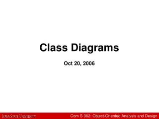
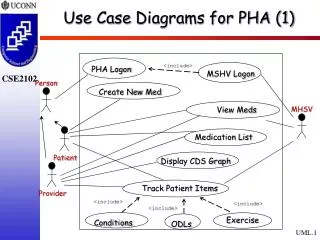
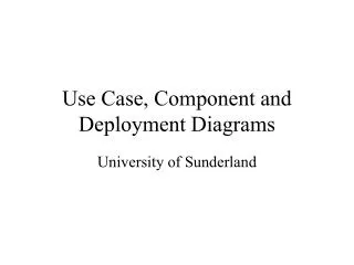
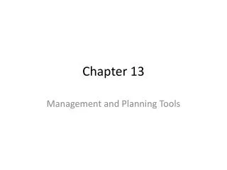
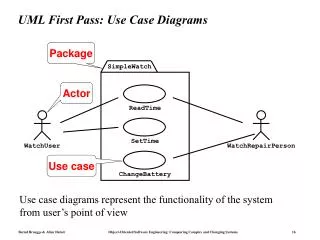
UML First Pass: Use Case Diagrams. Package. SimpleWatch. Actor. ReadTime. SetTime. WatchUser. WatchRepairPerson. Use case. ChangeBattery. Use case diagrams represent the functionality of the system from user’s point of view. UML First Pass: Class Diagrams. Class. Multiplicity.

E N D
UML First Pass: Use Case Diagrams Package SimpleWatch Actor ReadTime SetTime WatchUser WatchRepairPerson Use case ChangeBattery Use case diagrams represent the functionality of the system from user’s point of view
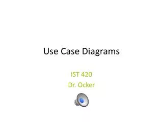
UML First Pass: Class Diagrams Class Multiplicity Association SimpleWatch 1 1 1 1 1 2 1 2 PushButton state push()release() LCDDisplay Battery load() Time now() blinkIdx blinkSeconds() blinkMinutes() blinkHours() stopBlinking() referesh() Attributes Operations Class diagrams represent the structure of the system
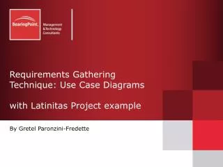
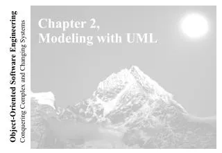
:SimpleWatch :LCDDisplay :Time :WatchUser pressButton1() blinkHours() pressButton1() blinkMinutes() pressButton2() incrementMinutes() refresh() pressButtons1And2() commitNewTime() stopBlinking() UML First Pass: Sequence Diagram Object Message Activation Sequence diagrams represent the behavior as interactions
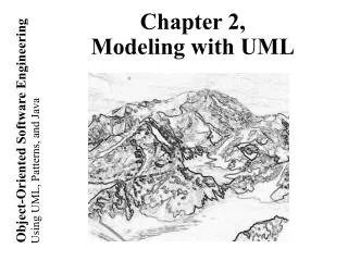
Increment Hours button2Pressed button1&2Pressed Blink Hours button1Pressed Increment Minutes button2Pressed button1&2Pressed Blink Minutes button1Pressed Increment Seconds button2Pressed Blink Stop Seconds Blinking UML First Pass: Statechart Diagrams State Initial state Event Transition Final state button1&2Pressed
Used during requirements elicitation to represent external behavior Actors represent roles, that is, a type of user of the system Use cases represent a sequence of interaction for a type of functionality The use case model is the set of all use cases. It is a complete description of the functionality of the system and its environment Passenger PurchaseTicket UML Second Pass: Use Case Diagrams
A use case represents a class of functionality provided by the system as an event flow. A use case consists of: Unique name Participating actors Entry conditions Flow of events Exit conditions Special requirements PurchaseTicket Use Case
Name:Purchase ticket Participating actor:Passenger Entry condition: Passengerstanding in front of ticket distributor. Passengerhas sufficient money to purchase ticket. Exit condition: Passengerhas ticket. Event flow: 1.Passengerselects the number of zones to be traveled. 2. Distributor displays the amount due. 3.Passengerinserts money, of at least the amount due. 4. Distributor returns change. 5. Distributor issues ticket. Use Case Example Anythingmissing? Exceptional cases!
<<extend>> relationships represent exceptional or seldom invoked cases. The exceptional event flows are factored out of the main event flow for clarity. Use cases representing exceptional flows can extend more than one use case. The direction of a <<extend>> relationship is to the extended use case Passenger PurchaseTicket OutOfOrder TimeOut Cancel NoChange The <<extend>> Relationship <<extend>> <<extend>> <<extend>> <<extend>>
An <<include>> relationship represents behavior that is factored out of the use case. An <<include>> represents behavior that is factored out for reuse, not because it is an exception. The direction of a <<include>> relationship is to the using use case (unlike <<extend>> relationships). Passenger PurchaseMultiCard PurchaseSingleTicket CollectMoney NoChange Cancel The <<include>> Relationship <<include>> <<include>> <<extend>> <<extend>>
TariffSchedule Table zone2price Enumeration getZones() Price getPrice(Zone) TariffSchedule zone2price getZones() getPrice() TariffSchedule Classes Name Signature Attributes Operations • A class represent a concept. • A class encapsulates state (attributes) and behavior (operations). • Each attribute has a type. • Each operation has a signature. • The class name is the only mandatory information.
Exhaust System Tailpipe Muffler Aggregation • An aggregation is a special case of association denoting a “consists of” hierarchy. • The aggregate is the parent class, the components are the children class. 1 0..2
TicketMachine 3 ZoneButton Composition • A solid diamond denote composition, a strong form of aggregation where components cannot exist without the aggregate.
Button CancelButton ZoneButton Generalization • Generalization relationships denote inheritance between classes. • The children classes inherit the attributes and operations of the parent class. • Generalization simplifies the model by eliminating redundancy.
Used during requirements analysis To refine use case descriptions to find additional objects (“participating objects”) Used during system design to refine subsystem interfaces Classes are represented by columns Messages are represented by arrows Activations are represented by narrow rectangles Lifelines are represented by dashed lines TicketMachine Passenger UML Sequence Diagrams selectZone() insertCoins() pickupChange() pickUpTicket()
TarifSchedule Display Passenger selectZone() lookupPrice(selection) price displayPrice(price) UML Sequence Diagrams: Nested Messages ZoneButton Dataflow • The source of an arrow indicates the activation which sent the message • An activation is as long as all nested activations …to be continued...