Information System Design IT60105
330 likes | 550 Views
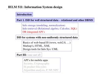
Information System Design IT60105. Lecture 8 Use Case Diagrams. Lecture #8. What is a use-case diagram? Example: On-line purchase (OLP) system Use-case diagram of OLP system Different components in a use-case diagram and their notations A use-case and its corresponding scenario

Information System Design IT60105
E N D
Presentation Transcript
Information System DesignIT60105 Lecture 8 Use Case Diagrams Information System Design IT60105, Autumn 2007
Lecture #8 • What is a use-case diagram? • Example: On-line purchase (OLP) system • Use-case diagram of OLP system • Different components in a use-case diagram and their notations • A use-case and its corresponding scenario • How to create a use case diagram? • Use case relationships • Use case packaging Information System Design IT60105, Autumn 2007
What is a Use Case Diagram? • The use case diagram is a diagram to model the use case view of a system. The behavior of the system under development (i.e. what functionality must be provided by the system) is documented in a use case diagram • Use case diagram illustrates the systems intended functions, its surroundings and relationship between the functions and surroundings • Example: • On-line purchase (OLP) system Information System Design IT60105, Autumn 2007
Intended functions Search items Place order Process order Control inventory Help on-line On-Line Purchase (OLP) System • Its surroundings • Customer • Manager • Payment processor Information System Design IT60105, Autumn 2007
Use Case Diagram of OLP System Information System Design IT60105, Autumn 2007
Usage of Use Case Diagrams • Use case diagram depicts the desirable functionalities (dynamic aspects) of an information system • Use case diagram very much resembles with the function oriented concepts (functional decomposition) of a system • Use case diagram is considered as the central part of the system model and provides vehicle used by the customer (or end users) and the developer discuss the system’s functionality and the behavior Information System Design IT60105, Autumn 2007
Different Components in the Use Case Diagram • Basic components in a use case diagram are • Use cases • Actors • Associations • System boundary boxes (optional) • Packages (optional) Information System Design IT60105, Autumn 2007
Use Case in Use Case Diagram • Use case • A use case describes a functionality provided by the system. The collection of use-cases for a system constitute all the defined ways the system may be used • Formal definition • A use case is a sequence of transactions performed by the system that yields a measurable result of values for a particular user (actor) Notation: A use case is represented by an oval Information System Design IT60105, Autumn 2007
Actor in Use Case Diagram • Actor • An actor is a person, organization, or external system that plays a role in one or more interaction with the system • Note: Actors are not part of the system; they represent any one or any thing that interact with the system Notation: Actor can be represented as a stick man Information System Design IT60105, Autumn 2007
Association in Use Case Diagram • Association • Associations between actors and use cases are indicated in use case diagrams by solid lines. An association exists whenever actor involved with an interaction described by the use case • Associations are modeled as lines connecting use cases and actor to one another, with optional arrowhead on one end of the line. The arrowhead is used to indicating the direction of the relationship or to indicate the primary actor within the use case Notation Information System Design IT60105, Autumn 2007
System Boundary Box in Use Case Diagram • System boundary boxes • It is an optional thing in a use case diagram to draw a rectangle around the use cases and to indicate the scope of the system Notation Information System Design IT60105, Autumn 2007
Packages in Use Case Diagram • Packages • Packages enable to organize model elements into groups Notation Packages are depicted as a file folders and can be used on any of the UML diagrams, including both use case diagrams, class diagrams etc. Note: Usually package can be used when a UML diagram is quite large and can not be accommodated on a single page, or organize a large diagram into smaller ones Information System Design IT60105, Autumn 2007
Packages in Use Case Diagram • Example Information System Design IT60105, Autumn 2007
Scenario and Use Case • Scenario • A scenario is a sequence of steps describing an interaction between a user and system • Corresponding to a use case, there is a number of scenarios. All scenario are described by means of a textual description or other artifacts Information System Design IT60105, Autumn 2007
Example: Scenario and Use Case Example: In OLP system Some scenarios are • Customer browses though a catalog and select the items • Customer options for check out • Customer fills shipping information ( address, date of delivery, email, etc.) • System present full pricing information, date of delivery, etc. • Customer fills credit card information • System authorizes purchase • System confirms sales immediately • System confirm sale by sending email by customer Note: From one scenario, another scenario can arise. For example: at 3 incomplete information, at 6 authorization fails etc. Information System Design IT60105, Autumn 2007
How to Create a Use Case Diagram? • Three steps • Identify all actors • Identify all use cases • All associations between actors and use cases • Study carefully the requirement analysis and specification (SRS) to identify all these Information System Design IT60105, Autumn 2007
Identifying all Actors • The following questions may be used to help identify the actors for a system • Who will use the system? • Where in the organization in the system used? • Who will supply, use, update the information in the system? • Who will support and maintain the system? • Does the system use external resource? • Does one person play several roles? • Does several persons play several roles ? ….. etc. Information System Design IT60105, Autumn 2007
Identifying all Use Cases • The following questions may be used to help identify the actors for a system • What are the functional requirements? • What are the tasks of each actor? • Will any actor create, change, store, remove, or read information in the system? • What use case will accomplish the actors requirements? ….etc. Information System Design IT60105, Autumn 2007
Identifying all Associations • There will be an association between an actor and a use case, if there is • any correspondence/communication between the two • information storing/updating ….etc. Information System Design IT60105, Autumn 2007
Use Case Relationships • In addition to association relationship ( which may exist between an actor and use-case) to represents a communication between an actor and a use-case, there are other three types of relationships may exist between use-cases • Include • Extend • Generalization Information System Design IT60105, Autumn 2007
Include Relationship • A use case in UML is same as the function in structured design • Like structured design a use case can be decomposed into sub use cases • Include • To represent that a use case is composed of (reuse) Information System Design IT60105, Autumn 2007
Include Relationship • Further • Multiple use cases may share a piece of some common functionality. This functionality is placed in a separate use case rather than documenting it in every use case that needs it • Include relationships are created between the new use case and any other use case that “uses” its functionality Information System Design IT60105, Autumn 2007
Example: Include Relationship Information System Design IT60105, Autumn 2007
Extend Relationship • The extended relationship is used to describe a variation on normal behavior and one wish to use the more controlled form. Usually extended relationship is considered to depict the following situations • Optional behavior • Behavior that run only under certain consideration • Several control flows may be run based on actor selection Information System Design IT60105, Autumn 2007
Example: Extend Relationship Information System Design IT60105, Autumn 2007
Example: Extend Relationship Information System Design IT60105, Autumn 2007
Generalization Relationship • Generalization relationship is very similar to the inheritance relationship as in classes • Inheritance relationship is used to model generalization/ specialization of use case or actors Information System Design IT60105, Autumn 2007
Generalization Relationship • The generalization relationship can also be extended to actor Information System Design IT60105, Autumn 2007
Use Case Packaging • Packaging is the mechanism in UML to manage complexity • When there are too many use cases in the use case diagram, it is better to package the related use cases so that it can be better documented Information System Design IT60105, Autumn 2007
Example: Use Case Packaging Information System Design IT60105, Autumn 2007
Problems to Ponder • Draw the use case diagram for • Library Information System • Bank ATM Information System Design IT60105, Autumn 2007