Download
1 / 25
260 likes | 421 Views
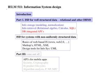
Information System Design IT60105. Lecture 16 Activity Diagrams. Lecture #16. What is an activity diagram? Example: Student Enrollment in IIT (SEIIT) Activity diagram for a use case in SEIIT Basic components in an activity diagram and their notations

E N D
Information System DesignIT60105 Lecture 16 Activity Diagrams Information System Design IT60105, Autumn 2007
Lecture #16 • What is an activity diagram? • Example: Student Enrollment in IIT (SEIIT) • Activity diagram for a use case in SEIIT • Basic components in an activity diagram and their notations • Managing the large activity diagram: Swim Lane • Activity diagram vs. Flow chart Information System Design IT60105, Autumn 2007
What is an Activity Diagram? • Activity diagrams represent the dynamic (behavioral) view of a system • Activity diagrams are typically used for business (transaction) process modeling and modeling the logic captured by a single use-case or usage scenario • Activity diagram is used to represent the flow across use cases or to represent flow within a particular use case • UML activity diagrams are the object oriented equivalent of flow chart and data flow diagrams in function-oriented design approach • Activity diagram contains activities, transitions between activities, decision points, synchronization bars, swim lanes and many more… Information System Design IT60105, Autumn 2007
Student Enrollment in IIT (SEIIT) Information System Design IT60105, Autumn 2007
SEIIT System • Here different activities are: • Received enrollment form filled by the student • Registrar checks the form • Input data to the system • System authenticate the environment • Pay fees by the student • Registrar checks the amount to be remitted and prepare a bill • System acknowledge fee receipts and print receipt • Hostel allotment • Allot hostel • Receive hostel charge • Allot room • Medical check up • Create hostel record • Conduct medical bill • Enter record • Issue library card • Issue identity card Information System Design IT60105, Autumn 2007
Activity Diagram for the Use Case in SEIIT Information System Design IT60105, Autumn 2007
Basic Components in an Activity Diagram • Initial node • The filled circle is the starting point of the diagram • Final node • The filled circle with a boarder is the ending point. An activity diagram can have zero or more activity final state. • Activity • The rounded circle represents activities that occur. An activity is not necessarily a program, it may be a manual thing also • Flow/ edge • The arrows in the diagram. No label is necessary Information System Design IT60105, Autumn 2007
Basic Components in an Activity Diagram • Fork • A black bar ( horizontal/vertical ) with one flow going into it and several leaving it. This denotes the beginning of parallel activities • Join • A block bar with several flows entering it and one leaving it. this denotes the end of parallel activities • Merge • A diamond with several flows entering and one leaving. The implication is that all incoming flow to reach this point until processing continues Information System Design IT60105, Autumn 2007
Basic Components in an Activity Diagram • Difference between Join and Merge • A join is different from a merge in that the join synchronizes two inflows and produces a single outflow. The outflow from a join cannot execute until all inflows have been received • A merge passes any control flows straight through it. If two or more inflows are received by a merge symbol, the action pointed to by its outflow is executed two or more times Information System Design IT60105, Autumn 2007
Basic Components in an Activity Diagram • Decision • A diamond with one flow entering and several leaving. The flow leaving includes conditions as yes/ no state • Flow final • The circle with X though it. This indicates that Process stop at this point • Swim lane • A partition in activity diagram by means of dashed line, called swim lane. This swim lane may be horizontal or vertical Information System Design IT60105, Autumn 2007
Detailed Activity Diagram of SEIIT Information System Design IT60105, Autumn 2007
Detailed Activity Diagram of SEIIT Information System Design IT60105, Autumn 2007
Detailed Activity Diagram of SEIIT Information System Design IT60105, Autumn 2007
Activity Diagram of SEIIT with Swim Lane Information System Design IT60105, Autumn 2007
Some more features in Activity Diagrams Information System Design IT60105, Autumn 2007
Object and Object Flow • An object flow is a path along which objects can pass. An object is shown as a rectangle • An object flow is shown as a connector with an arrowhead denoting the direction the object is being passed. Information System Design IT60105, Autumn 2007
Input and Output Pin • An object flow must have an object on at least one of its ends. A shorthand notation for the above diagram would be to use input and output pins Information System Design IT60105, Autumn 2007
Data Store • A data store is shown as an object with the «datastore» keyword Information System Design IT60105, Autumn 2007
Expansion Region • An expansion region is a structured activity region that executes multiple times. Input and output expansion nodes are drawn as a group of three boxes representing a multiple selection of items. The keyword iterative, parallel or stream is shown in the top left corner of the region Information System Design IT60105, Autumn 2007
Exception Handling • Exception Handlers can be modeled on activity diagrams as in the example below Information System Design IT60105, Autumn 2007
Interruptible Activity Region • An interruptible activity region surrounds a group of actions that can be interrupted. In the very simple example below, the Process Order action will execute until completion, when it will pass control to the Close Order action, unless a Cancel Request interrupt is received which will pass control to the Cancel Order action Information System Design IT60105, Autumn 2007
An Example • Identify the business logic in the activity diagram shown below Information System Design IT60105, Autumn 2007
Importance of Activity Diagram • An activity diagram can depict a model in several ways • It can also depicts “Basic course of action” as well as “detailed courses” • Activity diagram can also be drawn that cross several use cases, or that address just a small portion of use case • Activity diagrams are normally employed in business process modeling. This is carried out during the initial stages of requirement analysis and specification • Activity diagrams can be very useful to understand the complex processing activities involving many components • The activity diagram can be used to develop interaction diagrams which help to allocate activities to classes Information System Design IT60105, Autumn 2007
Problems to Ponder • How activity diagram related to flow chart? How it defers from flow chart? • How methods in classes and activities can be correlated? Information System Design IT60105, Autumn 2007
Problems to Ponder • Draw the activity diagrams for • Library Information System • Bank ATM Information System Design IT60105, Autumn 2007