Download
1 / 44
440 likes | 601 Views
Hybrid Secure-Entry System. By Group 8: Mark Bronsberg & Nick Stout ECE 445 – Senior Design Project December 1 st , 2005. Introduction. Security is a major issue in the 21 st century e.g., car alarms, power door locks, card readers, even video surveillance Biometrics are a good ‘ key ’

E N D
Hybrid Secure-Entry System By Group 8: Mark Bronsberg & Nick Stout ECE 445 – Senior Design Project December 1st, 2005
Introduction • Security is a major issue in the 21st century • e.g., car alarms, power door locks, card readers, even video surveillance • Biometrics are a good ‘key’ • Hard to fake, nothing to carry • Radio Frequency IDentification (RFID) is currently a very popular technology • I-Pass, Inventory Management, Theft Prevention
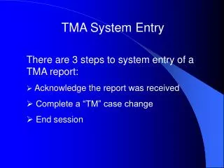
Objective We wanted to use a combination of portable authentication and biometric verification to form a more secure, stable, and easy-to-use security system. In particular, we planned on using RFID tags and a user’s voice to confirm a valid entry.
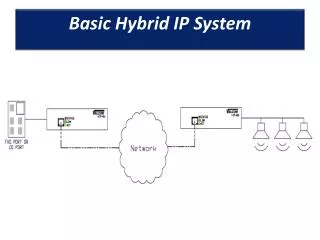
TI RFID Tag Logitech Camera Relay (for solenoid) TI RFID Reader (S6500 Series) LCD PIC16F877A Microcontroller PC Microphone - - - - - - - - System Description Antenna
System Description • Hardware interfacing: • TI RFID Equipment • PC • Relay & Driver • LCD • Software interfacing: • MATLAB Image acquired from Texas Instruments (http://www.ti.com/rfid/graphics/productImages/stu-650a.jpg)
Features • Uses RFID Authentication • RFID Tags are passive - no need to replace batteries • RFID Tags have a unique ID for users to be recognized, and cannot easily be spoofed • Hands-free – larger tags can be easily read up to 1.5 feet away from antenna through pockets.
Features • Uses Biometric (Voice/Face) Verification • Neither voice nor face can be easily faked • Verification is fast – Less than 2 seconds • Requires little work by the user • Items cannot be forgotten at home
Features • Other Security Features • Times out during verification (if no data is received) • Too many attempts → Locks user out • Easily adaptable for more forms of security with serial interfacing • Name/password database is stored on PIC for ultimate security
General Flow of Process Start RFID ready Ping RFID reader Set lockout bit 1 Valid RFID? No Yes Greet user, Request PW Check Password Lockout Timeout Unlock relay Wait 8s Lock relay
Hardware Overview LCD Relay Driver PIC16F RS232 Line Driver 10 MHz Oscillator
Hardware Overview • PIC communicates over two UARTs • Hardware UART communicates with RFID Reader • Software UART communicates to PC • MAX232 driver raises +5V TTL levels to +10V RS232 levels • PIC sends user instruction to LCD buffer • PIC opens/closes relay contacts (with relay driver circuit)
Relay Driver • PIC sends a high (5V) through resistor • Current is amplified by BJT • Current flows through coil and closes relay contacts • Diode stops flyback current from destroying other components
RFID Reader • Reader runs in Buffered Read mode • Operates at 13.56 MHz • Power usage varies by activity: • Scanning peaks around 4.3W, powering up peaks around 24W • Reader is responsible for activating the transponders and receiving their data. • Requires matched-Z antenna (50 Ω)
RFID Tags • Tags operate at 13.56 MHz • Activated by Reader • Receives power from antenna and transmits back • Comes in 4 sizes for different configurations • Tags can store packets of data Image acquired from Texas Instruments (http://www.ti.com/rfid/docs/manuals/refmanuals/hfi_inlays_ref_guide.pdf)
RFID Antenna • ~50 Ω characteristic impedence (matched) • 13.56 MHz operating frequency • Very placement-sensitive • Near-field • λ= 22 m • Tested read distance ≈ 0.46 m
Tag Range Tags held near antenna Tags kept in pocket • Antenna can receive larger tags up to about 1.5 feet • Smaller tags shouldn’t be used in security system, as they don’t meet our demands (1’ minimal read distance)
Biometric Authentication • Originally planned to use the TI-54x DSP for voice recognition • embedded, portable system • 1/8’’ audio connection • serial port • Misplaced emphasis on learning ECE 420 labs and assembly lost time • Chose to implement design with MATLAB and add face recognition
Cepstral Analysis Cepstral Analysis for Voice Recognition speech FFT log10 Mel FFT -1 cepstrum
Cepstral Analysis Cepstral Analysis for Voice Recognition speech FFT log10 Mel FFT -1 cepstrum • Uses source-filter model of speech production: • s = speech signal heard by ear/system • h = transfer function of vocal tract, glottis • e = excitation signal (pitch of speech)
Cepstral Analysis Cepstral Analysis for Voice Recognition speech FFT log10 Mel FFT -1 cepstrum • Uses source-filter model of speech production:
Cepstral Analysis Cepstral Analysis for Voice Recognition speech FFT log10 Mel FFT -1 cepstrum • Uses source-filter model of speech production:
Cepstral Analysis Cepstral Analysis for Voice Recognition speech FFT log10 Mel FFT -1 cepstrum • Convert to Mel-frequency scale • approximates the manner in which humans hear sound • Low frequencies: variations are distinct • High frequencies: variations are less clear
Cepstral Analysis Cepstral Analysis for Voice Recognition speech FFT log10 Mel FFT -1 cepstrum • Uses source-filter model of speech production: • It is typical to use the first 12 or 13 cepstral coefficients.
Cepstral Analysis • cepstral coefficients → identification vector (usually averaged) • The system “learns” each user by storing ID vectors • New recordings are compared to this ID vector by calculating the Euclidean distance. • We set a threshold of ev < 1.0
Cepstral Analysis • What went wrong with our demo? • Misunderstanding of the theory • “Cepstral coefficients” not defined in most papers; usually understood to mean “cepstral values” • We incorrectly understood them to be the locations of the largest peaks in the cepstrum
Face Recognition • Requires even less work by the user than voice recognition; not affected by illness • Methods: • Feature extraction, measurements • 2-D Fourier analysis and correlation • Eigenfaces
The Method of Eigenfaces • M. Turk and A. Pentland, “Eigenfaces for Recognition”, Journal of Cognitive Neuroscience, March 1991. • Based on principal component analysis (PCA)
The Method of Eigenfaces • PCA, an easily-visualized 2-dimensional case: • We have sets X and Y Image acquired from: http://www.cs.otago.ac.nz/cosc453/student_tutorials/principal_components.pdf
The Method of Eigenfaces • PCA, an easily-visualized 2-dimensional case: • We have sets X and Y • Find covariance matrix • Compute eigenvectors • Decreasing variance Image acquired from: http://www.cs.otago.ac.nz/cosc453/student_tutorials/principal_components.pdf
The Method of Eigenfaces • Forming eigenfaces for images: • “Training set” of 16 images: G1,…,G16. Average Y • Find covariance matrix C, eigenvectors uk • These eigenvectors are called the “eigenfaces” • These orthonormal vectors form a subspace • Project each new image, G, onto this “face space” • wk = ukT(G - Y) This operation is fast. • W = [w1, …, w16]
The Method of Eigenfaces • Each person has an W vector, “learned” by the system through a few initial images • We use Euclidean distances, as we did for voice recognition • We use an ef = 65 • Distances between different users are typically >150
The Method of Eigenfaces The Average Face, Y
Some Eigenfaces 9 7 14 12
Voices vs. Faces • Voice Recognition • Fairly robust • Difficult to remove background noise • Limited to 12 or 13 cepstral coefficients • Face Recognition • More robust • Easier to remove background • Limited to M eigenfaces (M = # training images)
Successes & Failures • Stable security program on PIC • Interfaces easily with two separate devices • Can drive a high current device (i.e. electronic lock) • Can accurately recognize user voices and faces • Biometric verification is fast • Not easily programmable • Troubles with learning DSP hardware • Interfacing between MATLAB and PIC incomplete • Requires lab power supply
Challenges • #1 Challenge: Time management • Communication with RFID Reader in Buffered Read Mode • Secrets and mysteries of PIC programming • Secrets and mysteries of DSP assembly • Understanding of the algorithms • Fighting wiring impatience
Future Developments • Programmability by administrator(s) • Case with power supply • MATLAB code ported to DSP for portability • Further testing of fully integrated system • Voice/Face verification (matching RFID tags) • Electronic door lock attached to relay • More secure biometrics • Iris or retinal scan
Credits • Alex Spektor • Professor Swenson • Professor Douglas Jones • Lindsay I. Smith (PCA tutorial) • CCS Forum Users • Ttelemah & PCM Programmer • Tony Wilson from Texas Instruments