Download
1 / 40
420 likes | 680 Views
TCP TCP Congestion Control & Quality of Service . Presenting By:-. Aditya K umar D akua Mitali S amal Rahul Kumar Nayak Sribishnu Das Omm Prasad Routray. Contents. TCP/IP Model Protocols using in TCP/IP model. Layers description

E N D
TCP TCP Congestion Control & Quality of Service Presenting By:- Aditya Kumar Dakua Mitali Samal RahulKumar Nayak Sribishnu Das Omm Prasad Routray
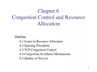
Contents • TCP/IP Model • Protocols using in TCP/IP model. • Layers description • Difference between TCP/IP & OSI. • TCP(Transmission Control Protocol) • TCP Segment format • Congestion Control • Open-Loop • Closed-Loop • Causes of congestion • General Policies of congestion control • QOS(Quality Of Service) • Techniques for achieving good quality of service.
TCP/IP • The TCP/IP protocol suite was developed prior to the OSI model. • The original TCP/IP protocol suite was defined as having four layers: host to network, internet, transport and application. • But as compared to OSI model TCP/IP has five layers.
APPLICATION Application layer PRESENTATION SMTP FTP HTTP DNS SNMP TELNET SESSION TRANSPORT SCTP TCP UDP IP ICMP IGMP NETWORK RARP ARP DATA LINK Host-to-network PHYSICAL
PROTOCOLS USING IN TCP/IP MODEL • SMTP- Simple Mail Transfer Protocol • FTP- File Transfer Protocol • HTTP- Hyper Text Transfer Protocol • DNS- Domain Name Service/System • SNMP- Simple Network Management Protocol • TELNET- Terminal Network • SCTP- Stream Control Transmission Protocol • TCP- Transmission Control Protocol • UDP- User Datagram Protocol • ICMP- Internet Control Message Protocol • IGMP- Internet Group Message Protocol • RARP- Reverse Address Resolution Protocol • ARP- Address Resolution Protocol • IP- Internet Protocol
LAYERS DESCRIPTION PHYSICAL AND DATA LINK LAYER • TCP/IP does not define any specific protocol. • A network in TCP/IP internetwork can be local-area network or a wide-area network. NETWORK LAYER • TCP/IP supports the internetworking protocol. • IP in turn uses four supporting protocols: ARP,RARP,ICMP and IGMP.
TRANSPORT LAYER • It is represented in TCP/IP by two protocols. • IP is host to host protocol. • UDP and TCP are transport level protocols. APPLICATION LAYER • It is equivalent to combined session, presentation and application layer in the OSI model.
TCP/IP • Basically It has 4 Layers. Such as Application, Transport, Internet, Network access Layer. • Application layer of TCP/IP model is combination of 3 layers, i.e Application, Presentation, Session Layer • The data link & physical layer are combinely to form Network access layer. • When TCP/IP compared with the OSI model then it acts as 5 layer. i.e Application, Transport, Internet, Data link & Physical Layer. OSI • It has 7 Layers Such as Application, Presentation, Session, Transport, Network, Data link, Physical Layer. • In this model each layer perform a specific task by the respective layer within their bounded area.
TCP (Transmission control protocol) • TCP is a transport layer protocol which provides connection-oriented service. • It is a process-to-process or program-to-program protocol. • It creates a virtual connection between two TCPs to send data. • This protocol provides error recovery , flow control & reliability which are not available in UDP. • TCP is the protocol used by major Internet applications such as the world wide web, email, remote administration & file transfer.
Cont… • It is a sliding window protocol that provides handling for both timeouts and retransmissions. • TCP establishes a full duplex virtual connection between two endpoints. Each endpoint is defined by an IP address and a TCP port number. • The operation of TCP is implemented as a finite state machine. • It does not support multicasting & broadcasting. • TCP maintains a checksum on its header & data. • A TCP connection is a byte stream not a message stream. A Stream of 8-bit bytes is exchanged across the TCP connection between the two applications.
HEADER FORMAT OF TCP (TCP SEGMENT FORMAT) Header Data Destination port address 16 bits Source port address 16 bits Sequence number 32 bits Acknowledgement number 32 bits ACK Hlen 4 bits Reserved 6 bits URG PSH RST SYN FIN Window size 16 bits Urgent pointer 16 bits Check sum 16 bits Options & Padding
Source port address • This is a 16-bit field that defines the port number of the application program in the host that is sending the segment. Destination port address • This is a 16-bit field that defines the port number of the application program in the host that is receiving the segment. Sequence number • This 32-bit field defines the number assigned to the first byte of the segment which indicates the sequence number of that sequence.
Acknowledgement Number • 32-bit field. • It defines the byte number that the receiver of the segment is expecting to receive from the sender. HLEN(Header length) • This 4-bit field indicates the number of 4 byte words in the TCP header. Reserved • This is a 6-bit field reserved for future use.
Controlled field • This field defines six different control bits or flags. • URG • ACK • PSH • RST • SYN • FIN URG(Urgent) • Urgent pointer valid flag. • If it is set to 1 the urgent pointer field valid. ACK(Acknowledgement) • Acknowledgment number valid flag. • If the ACK flag is set to 1 the acknowledgement number field is valid.
PSH(Push) • Push flag • If the field is one then it will push the data segment for maximum range. RST(Reset) • Reset connection flag. • If this flag value is 1 then the connection is reset or reestablished. SYN(Synchronized) • Synchronize sequence numbers flag. • It is used for synchronized sequence number during connection. FIN • Terminate the connection. • End of data flag. • For termination of the connection this field is selected to 1.
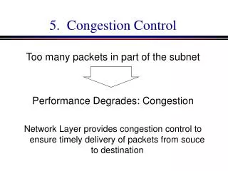
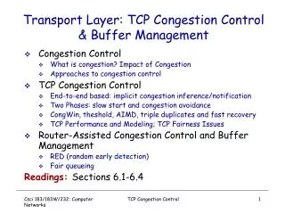
Congestion Control • It refers to the technology & mechanism that can either used to prevent congestion before it happens or removes congestion after it happens. • This can be broadly defined into two category. ->Open Loop ->Closed Loop
Congestion Control Open Loop (Before Congestion) Closed Loop (After Congestion) Retransmission Window Policy Acknowledgement Discarding Policy Admission Policy Back pressure Choke Packet Implicit Signaling Explicit Signaling Backward Forward
Open-Loop • In open-loop congestion control policies are applied to prevent congestion before it happens .in this mechanism congestion control is handled either the source or the destination. Retransmission Policy • It is sometimes unavoidable. If the sender feels that a send packet is lost or corrupted the packet needs to be retransmitted. Window Policy • According to this policy the type of window at the sender may also affect congestion . The selective repeat window is better than the Go-Back-N window for congestion control.
Acknowledgement Policy • This policy imposed by the receiver may also affect congestion .if the receiver does not acknowledge every packet it receives, it may slow down the sender & prevent congestion. Discarding policy • A good discarding policy by the routers may prevent congestion & at the same time may not harm the integrity of the transmission. Admission Policy • An admission policy ,which is a quality of service mechanism can also prevent congestion in virtual circuit networks switches in a flow first check the resource requirement of flow before admitting to the network.
Closed loop • This congestion control mechanisms try to alleviate congestion after it happens . several mechanisms have been used by different protocols. Back Pressure • It refers to a congestion control mechanisms in which a congested node stops receiving data from the immediate upstream node or nodes . this may causes the upstream node or nodes to become congested. • In turn reject data from their upstream node or nodes . this technique can be applied only to virtual circuit networks in which each node knows the upstream node from which a flow of data is coming.
Backpressure method for alleviating congestion • Choke Packet • It is a packet sent by a node to the source to inform it of congestion. In this method the warning is from the router, which has encountered congestion, to the source station directly. The intermediate nodes through which the packet has traveled are not warned.
Choke Packet • Implicit signaling • There is no communication between the congested node or nodes & the source . The source guesses that there is congestion some where in the network from other symptoms.
Explicit Signaling • In explicit signaling method the signal is included in the packets that carry data . It can occur in either the forward or the backward direction. • Backward Signaling • In this signaling a bit can be set in a packet moving in the direction opposite to the congestion. • Forward Signaling • In this a bit can be set in a packet moving in the direction of the congestion.
Causes of Congestion • If the rate at which packets arrive and queue of exceeds the rate at which packets can be transmitted the queue size grows , the delay experienced by a packet goes to infinite • The other causes of congestion is slow processor speed . if the router’s CPU speed is slow and performing task like queuing buffers table updating.queues are built up even through the line capacity is not fully utilised. • The bandwidth of the links is also important in congestion . The links to be used must be of high bandwidth to avoid the congestion. • Any mismatch between parts of the system also causes congestion , up grading the processor’s speed but not changing the links or vice-versa will causes the congestion.
General Policies of Congestion Control • General policies of congestion control can be divided into two groups ->Open Loop ->Closed Loop Open Loop • Open loop solution attempt to solve the problem by good design in essence to make sure it dose not occur in the first place .once the system is up and running, midcourse corrections are not made. • Tools for doing open loop control include deciding when to accept new traffic, deciding when to discard packets and which ones ,and making scheduling decisions at various points in the network.
Closed Loop • Closed loop solutions are based on the concept of a feedback loop this approach has three parts when applied to congestion control. • Monitor the system to detect when and where congestion occurs. • Pass this information to place where action can be taken. • Adjust system operation to correct the problem. • Metrics to monitor the subnet for congestion are the average queue lengths , percentage of all packets discarded for lack of buffer space , average packed delay, the number of packets that time out are retransmitted etc.
Quality Of Service(QOS) • QOS is an internetworking issue that has been discussed more than defined . we can roughly defined QOS as something that a flow seeks to attain. • It requires a stream of packet from a source to a destination which is known as flow & application with their quality of service requirement. Techniques for achieving good quality of service There are 4 methods for improving the QOS • Scheduling. • Traffic shaping. • Admission Control. • Resources Reservation.
Scheduling • The intermediate device like router switches processes the packets which are coming from different source host . so to process the packets to their corresponding receiver router should follow a good scheduling mechanism. • It is divided into 3 categories:- • FIFO Queue • Priority Queue • Weighted Queue
FIFO queue • In FIFO(First-in first-out) queuing packets wait in a buffer until the node is ready to process them . if the average arrival rate is higher than the average processing rate . the queue will fill up & new packets will be discarded.
Priority queuing • In priority queuing , packets are first assigned to a priority class each priority class has its own queue . The packets in the highest –priority queue are processed last . The system dose not stop serving a queue until it is empty . • A priority queue can provide better QOS than FIFO queue.
Weighted fair queuing • A better scheduling method is weighted pair queuing . In this technique the turning switch selects three packets from first queue then two packets from second queue &one packet from the third queue this cycle repeats until all the queues are empty.
Traffic Shaping • It is a mechanism to control the amount & the rate of the traffic sent to the network. • There are two techniques exists to shape traffic. • Leaky Bucket • Token Bucket
Leaky bucket implementation • A leaky bucket algorithm shapes brusty traffic into fixed-rate traffic by averaging the data rate. It may drop the packets if the bucket is full.
Token bucket • Token bucket is same as leaky bucket algorithm but it allows the flow of brusty traffic at a regulated maximum rate.
Admission Control • Admission control refers to the mechanism used by a router , or a switch to accept or reject a flow based on predefined parameters called flow specifications. • Resource Reservation • A flow of data needs resources such as buffer, bandwidth ,CPU time & so on. • The QOS is improved if these resources are reserved before hand.